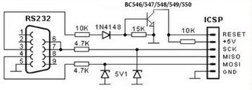
I am a bit confused on how this schematic works. It looks as if when we do not have any data coming in (i.e. 0V constant) from pin 3 on the DB-9 then the transistor will be off and the RESET will be pulled high as a consequence.
Now, say that the line 3 from the DB-9 goes HIGH, what happens then? Assuming the supply voltage from the connector is 5V, you can solve for the voltage at the base of the transistor, where you get ~2.57V.
Now that the transistor is on, how is the RESET driven low? Isn't it that the collector of a transistor is reverse biased in saturation mode? With that, we can approximate the collector voltage (and consequentially the RESET pin voltage) to be (2.57+0.7)V = 3.27V.
What is the threshold voltage for a RESET event generally?
Also, what are the purposes of each of the diodes in this schematic? Why is it needed to have a diode inline with the resistors off pin 3? Why are there diodes on pins 7 and 4?

