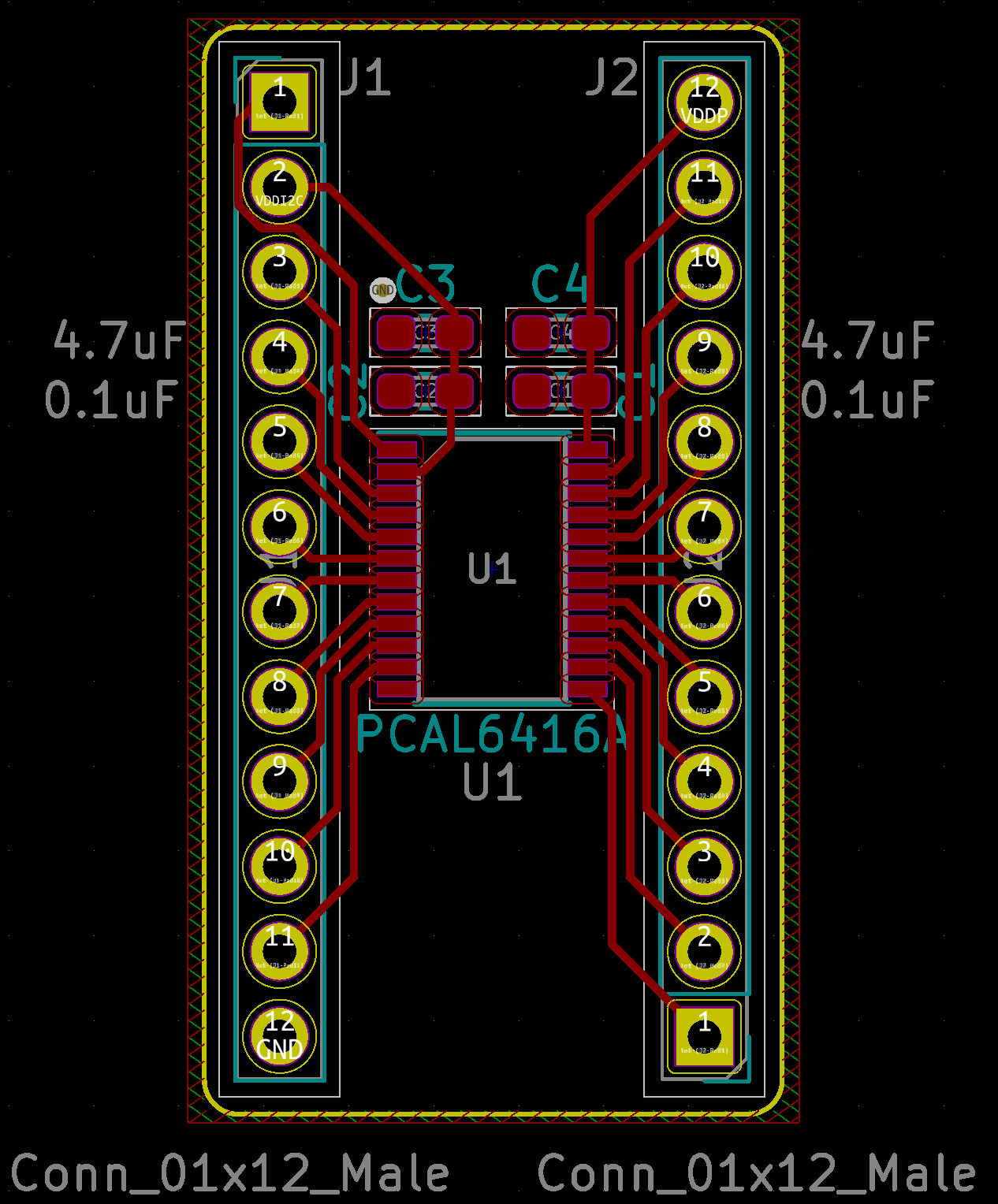
I'm working on a PCB that allows me to attach a TSSOP IO expander to a breadboard more easily for experimenting. I asked a question regarding the configuration of decoupling capacitors for an IC with 2 supply pins.
One of the recommendations was to add ground pours to the top and bottom layers of the PCB to create low impedance ground connections for the decoupling capacitors and to tie the top and bottom layers with several stitching vias.
How do I know how many stitching vias to place and how do I know where to place them?
Here is what the board looks like so far:

Edit:
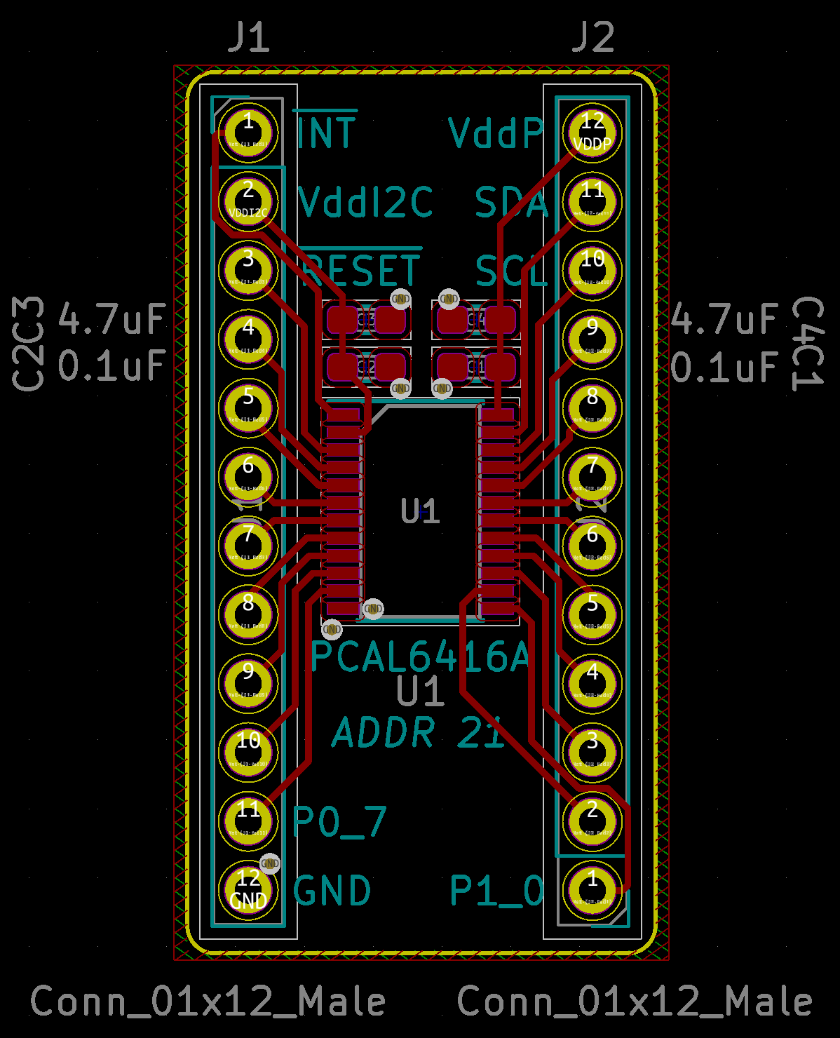
Because I'm new to electrical engineering (I'm barely at hobbyist level), it really helps me to see solutions visually. For folks finding this in the future, here's what my latest state is:

