Question: What size of fly-back diode do I need for my inductive load?
My Answer: Fly-back diodes are sized based on power dissipation
\$P = 1/10(I^2)R\$
P: power dissipated in fly-back diode
I: steady state current flowing through the inductor (fly-back diode not conducting)
R: resistance of the fly-back diode in conduction
Proof:
The fly-back diode will be held at a constant temperature; diodes have a constant resistance in conduction when held at a constant temperature. (if the temperature changes, so does the diodes resistance)
Now the conducting diode behaves as a resistor so the question becomes: How much power do I need to dissipate in my diode's internal resistance?
By observing a series RL curve, we know that the inductor discharges or charges in 5 time constants and one time constant is equal to the inductance divided by the series resistance (\$T = L/R\$).
Some math people told us that the energy stored in an inductor is:
\$E = (1/2)L(I^2)\$. Here E is in joules, L is in Henrys. They also said that power is energy per second (\$P = E/time\$). Here, power is in watts.
So... if our understanding of physics is working... the time in which the inductor discharges is: \$5(L/R)\$ seconds, and a stored energy of \$(1/2)L(I^2)\$ joules is released in that time. Here R is the resistance of the fly-back diode in conduction, I is the current flowing through the fly-back diode and L is the inductance supplying the current.
If we solve for the power, something very interesting happens...
\$P = ((1/2)L(I^2)R) / (5L)\$ Here, L cancels out and \$P = 1/10(I^2)R\$. We know that R is the resistance of the diode in conduction and I is the current flowing through the diode during the discharge. But now, what is the diode current during discharge?
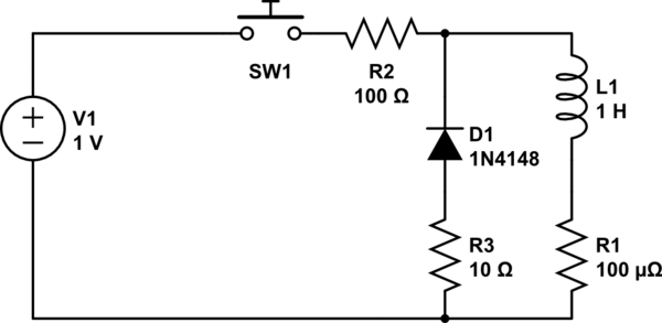
Consider a circuit as such:

simulate this circuit – Schematic created using CircuitLab
R1 is the internal resistance of L1, and R2 is our charging resistance. D1 functions as the fly-back diode, and R3 is the resistance of D1 in conduction.
If the switch is closed and we wait forever, a current of 10mA flows through the circuit, and the inductor stores an energy of 50μJ (50 micro Joules).
Using conservation of energy theory:
If the switch is opened, the inductor reverses polarity to try to maintain the 10mA current. The fly-back diode is biased into conduction, and an energy of 50μJ is dissipated through the diode resistance in \$5(L/R) = 500\mathrm{ms}\$. The power dissipated in the diode is 50μJ / 500ms = 100μW (100 micro watts).
\$(1/10) (10\mathrm{mA} ^2) (10\mathrm{ohms}) = 100\mathrm{\mu W}\$
So to answer the last question: the diode current during discharge can be thought of as equal to the steady state charging current of 10mA when using the equation: \$P = 1/10(I^2)R\$. While the current during the inductive discharge actually decreases exponentially and is not a steady 10mA, this simplification will allow for quick computations of the required diode power in a circuit by knowing the initial conditions.
Best of luck with your designs and never use technology for evil purposes.


