1
\$\begingroup\$

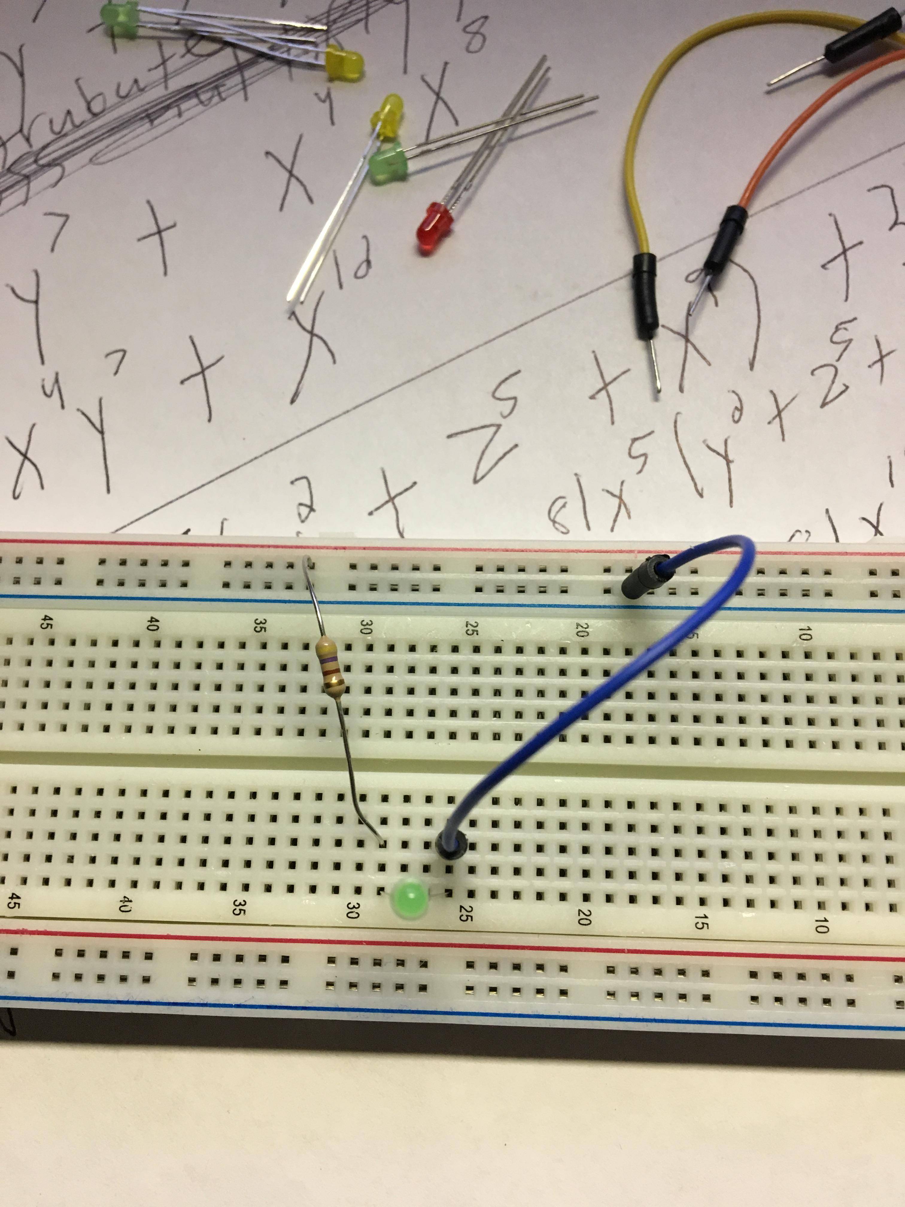
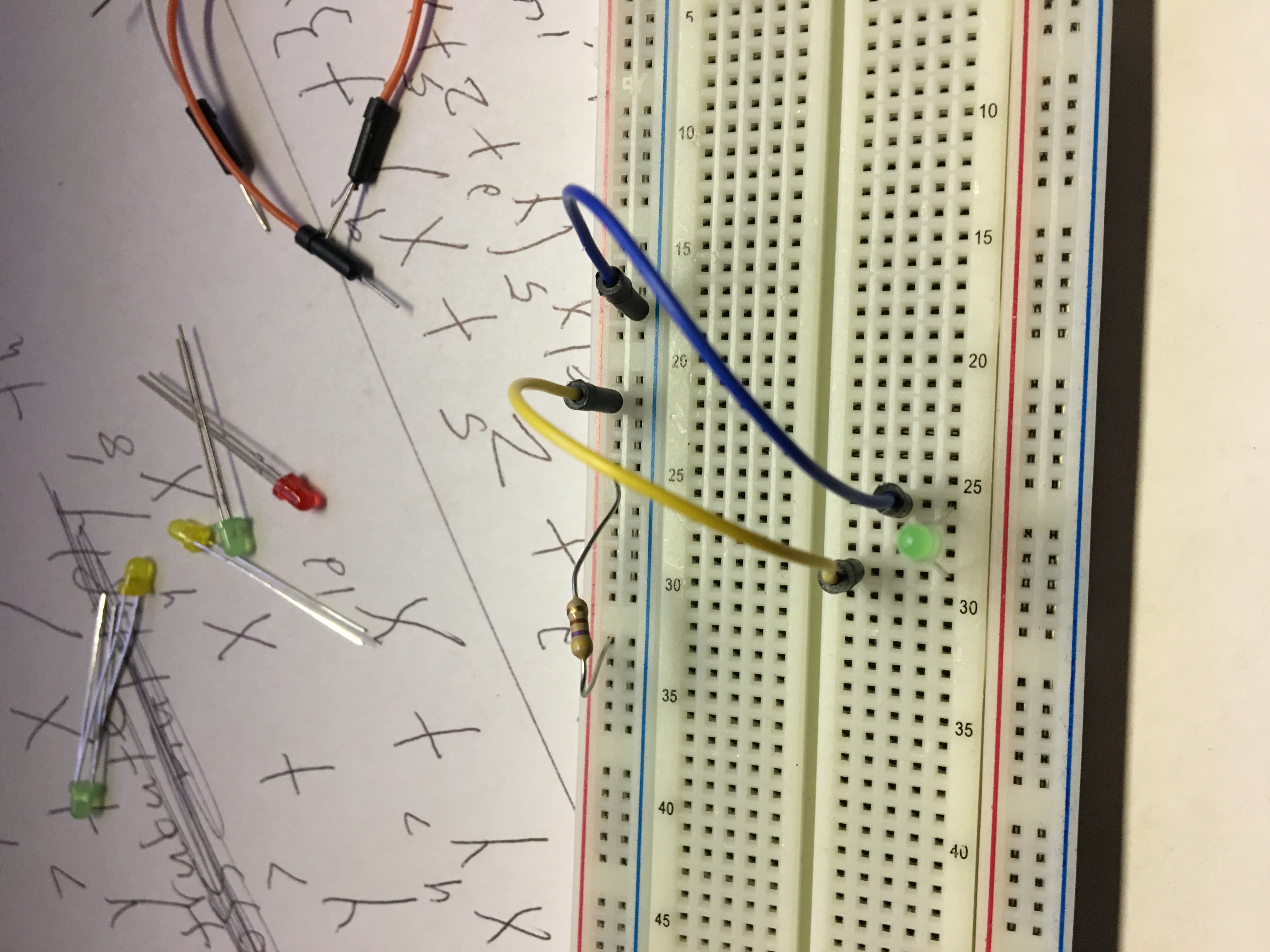
Please be kind as I am fairly new to electronics. Anyways, from what I read on multiple forums the rules are fairly straight forward, but I am puzzled as to why my led burnt out. So I connected the led with the resister and a 9V battery. My resister is 470 ohms. Led is 20 mAH with a 2v drop I think. Anyways, it was working fine with resister on breadboard going from the positive end of the led and then other end of resister going to the power (+) side of the breadboard. Then I went to see how I can make it different but still follow the same rules for my big project, which is multiple leds on an ugly sweater. Anyways, when I went to have a wire go from the positive end of the led to the power side of the breadboard and then placing the resister (both ends) on the power side of the breadboard, it burnt out my led for some reason. I want to know why this matters as it seems like it is still the exact same circuit. Also, as a side question, I can have as many leds as I want going to the resister but I lose time it will run on a single 9v battery right?

Good:

enter image description here

Bad:

enter image description here

\$\endgroup\$
7
  • \$\begingroup\$ From what it sounds is you placed the resistor on the positive line only and not in between the positive and the led. It would help a lot more if you had pictures or a diagram of how you are wiring it. As it is a little unclear \$\endgroup\$ Commented Dec 25, 2018 at 7:43
  • \$\begingroup\$ Yes you're right and then I connected a wire from the led to the positive line. I will see if I can upload a picture or two. \$\endgroup\$
    – Bob G.
    Commented Dec 25, 2018 at 7:51
  • \$\begingroup\$ If you connected the led directly to +9v power then your bi-passing the resistor. The resistor needs to be in between the +9v and the + side of the led. Or the ground and the ground side of the led. \$\endgroup\$ Commented Dec 25, 2018 at 7:53
  • \$\begingroup\$ I finally got enough charge. So here are the pictures. This seems like the same circuit but the bad one burns led out for some weird reason. There is the resister coming first, so its not bypassing. \$\endgroup\$
    – Bob G.
    Commented Dec 25, 2018 at 8:20
  • \$\begingroup\$ Ignore the math in the background btw. \$\endgroup\$
    – Bob G.
    Commented Dec 25, 2018 at 8:40

1 Answer 1

9
\$\begingroup\$

schematic

simulate this circuit – Schematic created using CircuitLab

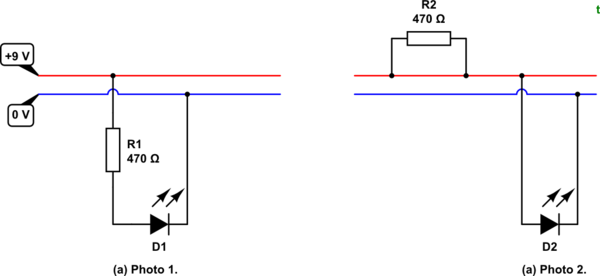
Figure 1. (a) Correct. (b) Incorrect.

In your first photo the resistor is in series with the LED. This is correct.

In your second photo your resistor is inserted into two points on the same track. The track is bypassing the resistor with its own much lower resistance (almost zero in comparison) so there is no current limiting to the LED. It should be clear from Figure 1b that you have applied 9 V directly across the LED.

The red and blue lines on the edge of the board indicate that those strips are continuous.

schematic

simulate this circuit

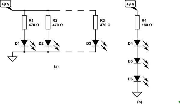
Figure 2. (b) is more efficient than (a).

You can extend your battery life by wiring your LEDs in strings of three. The same current can then light up three LEDs rather than one so your battery will last three times longer.

\$\endgroup\$
5
  • \$\begingroup\$ So the breadboard goes around then, I did not know that. I thought I wasn't bypassing because the resister was in front of the led essentially. Thanks. \$\endgroup\$
    – Bob G.
    Commented Dec 25, 2018 at 19:31
  • \$\begingroup\$ Your mind played a strange trick on you. On the one hand you realised that the power from your battery was being conducted along the red and blue rails because that's what you connected your circuit to. On the other hand you expected it to be broken somewhere between the two ends of the resistor inserted at a random point on the rail! \$\endgroup\$
    – Transistor
    Commented Dec 25, 2018 at 20:00
  • \$\begingroup\$ Yep, strange xd. But I know now why my second circuit was wrong. Thanks for the help. \$\endgroup\$
    – Bob G.
    Commented Dec 25, 2018 at 20:06
  • \$\begingroup\$ To be sure, a 9V would burn out a 3V LED very quickly right? \$\endgroup\$
    – jxramos
    Commented Dec 19, 2020 at 5:58
  • \$\begingroup\$ @jxramos, see lednique.com/current-voltage-relationships/iv-curves and the accompanying video. Thinking of an LED as "3 V" may get you into trouble. Instead you should think of the current rating and see what the voltage drop will be at that current. \$\endgroup\$
    – Transistor
    Commented Dec 19, 2020 at 8:47

Your Answer

By clicking “Post Your Answer”, you agree to our terms of service and acknowledge you have read our privacy policy.

Not the answer you're looking for? Browse other questions tagged or ask your own question.