19
\$\begingroup\$

I'm seeking for help here as I need a reliable answer to this. I need to get an input signal (low frequency 5v digital pulse), to a micro-controller from a (proximity) sensor situated in a distance from the control board.

I'll itemize the important points.

  • Max Tx distance : 50 m
  • Max digital pulse frequency : 10 Hz
  • Voltage range of the sensor : 5 to 30 v (it outputs the same voltage as supplied)
  • Max input to micro-controller : 5 v

For a simple, similar application, this is what I've done before; the sensor is supplied with 12 v. At the other end, the pulse (which now is 0-12v) is fed to the micro-controller through a 7805 regulator. That worked fine, but someone told me that method is not nice and not suited for reliable applications. I also feel that's ugly but i don't expect to mess around a lot with hardware, building separate circuitry etc... Can someone propose any better solution (or agree with mine :D).

I prefer a lot if i don't have to build any circuitry at all. If not possible, at least very simple one!(simple in the sense of hardware complexity. a circuit that don't need a PCB, just two wires here and there. That's why I love 7805 solution). However (unfortunately) the highest priority has to be given for reliability.

\$\endgroup\$
2
  • 3
    \$\begingroup\$ I do not see why you couldn't stay with your 7805 solution. I suspect that those who chide you about its use in this application are doing so because they have a hard time accepting the somewhat non conventional use of a voltage regulator. I see no issue with reliability either but would encourage the addition of a single small 0.1uF capacitor between the output and GND of the part to ensure stability. At 10Hz response rate I do not think the added capacitor will give any problems responding to the sensor pulse unless the pulse is very very narrow compared to the 100msec pulse rate. \$\endgroup\$ Commented Jan 17, 2013 at 13:22
  • \$\begingroup\$ @MichaelKaras great!!!!!!!!!!!!!!!!!!!!!!!!!!!!!! \$\endgroup\$ Commented Jan 18, 2013 at 17:09

2 Answers 2

21
\$\begingroup\$

A recommended approach would be to use an optocoupler followed by a comparator (eg. LM339), or better, an integrated part such as the Fairchild Semi FODM8071 logic gate output optocoupler.

The reason the optocoupler is recommended:

There is likely to be a ground potential difference over a 50 meter cable, also the possibility of picking up EMI over the long cable. The optocoupler eliminates any ground loop / potential mismatch concerns, as well as any need to precisely match the sensor's supply voltage to the microcontroller's.

The use of the opto will allow a higher voltage to be used for the sensor circuit, reducing EMI noise sensitivity.

An added benefit of the specific Fairchild part suggested above is its high noise immunity. This will result in a more stable signal acquisition, important given the distances involved.

FODM8071 is a 5-pin leaded SMT part, so using it is essentially like not having to build any additional circuit - you could wire the part and its few support discrete components up deadbug style, if you like, or put them together on a proto-board PCB.

\$\endgroup\$
7
  • 1
    \$\begingroup\$ this is probably the best solution, but if the cable has a ground conductor I do not think the potential mismatch would be significant. I'd try a resistive divider, that's the simplest solution, or the zener solution below which is even more precise. \$\endgroup\$ Commented Jan 17, 2013 at 9:04
  • 3
    \$\begingroup\$ Opto on the micro end is definitely the more elegant idea, I'd be paranoid (experience with telecomms / lightning / EMC) and add a couple of protection diodes/tranzorbs to save the opto from stray/reverse/over voltages. In general it's preferable to send a bigger signal down the line (send 12v and deal with it at the micro end) rather than start with a small signal and struggle to receive it reliably. It may also help your cause (noise immunity) if your sensor can drive some current down the line, EG through a 100Ohm termination resistor. See RS485 / RS422 standard for examples. \$\endgroup\$
    – John U
    Commented Jan 17, 2013 at 9:07
  • 1
    \$\begingroup\$ @CodenamedSC: search "midi microcontroller" or "midi schematic". Thousands of things out there. Another direction for further research is current loop, MIDI being simple example of such. \$\endgroup\$
    – Phil Frost
    Commented Jan 17, 2013 at 16:05
  • 1
    \$\begingroup\$ Some google/wikipedia search terms for you: MIDI, DMX, RS-232, RS-485, RS-422, 20mA current loop, differential signalling. \$\endgroup\$
    – John U
    Commented Jan 17, 2013 at 16:56
  • 1
    \$\begingroup\$ This is probably overkill for the application in question, though as mentioned there are applications where the extra cost and complexity is warranted. \$\endgroup\$ Commented Jan 17, 2013 at 17:10
12
\$\begingroup\$

Transmitting 10 Hz over 50 m is not a difficult problem, so you'll find there's numerous ways to do it. For a solution nearly as simple as the one you had before, I'd suggest a simple zener circuit.
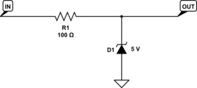
enter image description here

Like before, you'd simply supply your sensor with a voltage above 5 V. Say 6 - 12 V, and let this limiting circuit reduce the voltage to a level compatible with your downstream circuit. You'll need to adjust the value of R1 depending on the maximum (or desired) output current of your sensor circuit and the sensor voltage you choose. Cost can be very close to the 7805 solution, depending which zener you choose.

Like the optocoupler suggested in another answer, this provides protection against high-voltage transients induced on the cable, as the zener diodes can shunt these transients to ground. The optocoupler circuit can break ground loops between the sending and receiving systems, but if your 7805 solution is working the zener should work just as well.

Edit

If you're willing to do a little more work, you can improve this circuit by making it slightly more elaborate:
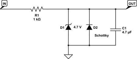
enter image description here

The added schottky diode protects your downstream circuit from negative transients. The zener would have done this, but would have only limitted transients to -0.7 V or so. The schottky will limit them to -0.3 or -0.2 V, which will be much safer for the downstream device if it's a typical logic gate.

The added 4.7 uF capacitor will help to reduce noise when the input is low.

Finally I adjusted the zener voltage down to be sure the output is safe for a 5 V logic gate, even allowing for some drift in the zener voltage, and increased R1 to reduce the current required to drive the input.

All of these things are subject to adjustment to fit the details of your sensor and downstream circuit.

Edit

A key point that I needed to think about overnight before I saw it:

Assuming your 50 m cable contains a signal wire and a ground (or return) wire, an optocoupler protects against common-mode transients (that is, when both the signal and ground wire together change voltage relative to the ground of the receiving circuit), while the zener circuit protects against differential transients where the signal wire voltage changes relative to the ground wire.

If a nearby lightning strike causes the ground and signal wire together to jump to 100 V for a millisecond, you need the optocoupler circuit to protect your receiver from damage.

But if a nearby motor switching on causes the signal wire to jump to 30 V above the ground wire, you need the zener circuit to protect your optocoupler from overload.

Of course, the type of cable and its environment determine which of these scenarios is more likely. If you're using general purpose control wire, either scenario is realistic. If you're using coaxial cable, common mode transients are more likely, but you should also consider the possibility of ESD damage due to handling when the cable isn't attached to the receiver, and also the effect if the cable is initially charged up when it is plugged in to the receiver.

\$\endgroup\$
13
  • 2
    \$\begingroup\$ 7805 is a power supply, this application relies on the 7805 behaving in an "ideal" way in a situation it's not designed for. Also, this is really not a good approach to solving the problem. The 7805 requires some current to operate (can your sensor source enough current? Does loading it change the sensor performance?) and prefers to see a load to drive into, and a smoothing cap to prevent oscillation / ripple. Anindo's suggestion is quite sensible for your stated application, Photon's answer is OK but assumes a very "clean" signal path (no protection). \$\endgroup\$
    – John U
    Commented Jan 17, 2013 at 9:17
  • 1
    \$\begingroup\$ @CodenamedSC - I can't really explain this large gap in your electrical knowledge/understanding here, I don't really have enough time, but please trust me the 7805 is a really poor way of doing this - both of the suggestions above are much better. \$\endgroup\$
    – John U
    Commented Jan 17, 2013 at 14:08
  • 1
    \$\begingroup\$ @CodenamedSC, This circuit is functionally equivalent to the 7805 idea. The main drawback of the 7805 is, the 7805 doesn't have any capability to absorb the transients that might be generated by interference on the cable. Either this circuit or the optocoupler circuit should be able to handle brief transients in the 100's of volts, which the 7805 is not designed for. \$\endgroup\$
    – The Photon
    Commented Jan 17, 2013 at 16:07
  • 1
    \$\begingroup\$ This is the better answer. It's simple, and the resistor at the receiving end will help absorb reflections, though better performance might be had if the resistor were moved to the sending end. \$\endgroup\$ Commented Jan 17, 2013 at 17:08
  • 3
    \$\begingroup\$ @ChrisStratton I think if I was using the optocoupler, I would add something close to this circuit in front to prevent transients blowing out the optocoupler. \$\endgroup\$
    – The Photon
    Commented Jan 17, 2013 at 17:14

Your Answer

By clicking “Post Your Answer”, you agree to our terms of service and acknowledge you have read our privacy policy.

Not the answer you're looking for? Browse other questions tagged or ask your own question.