5
\$\begingroup\$

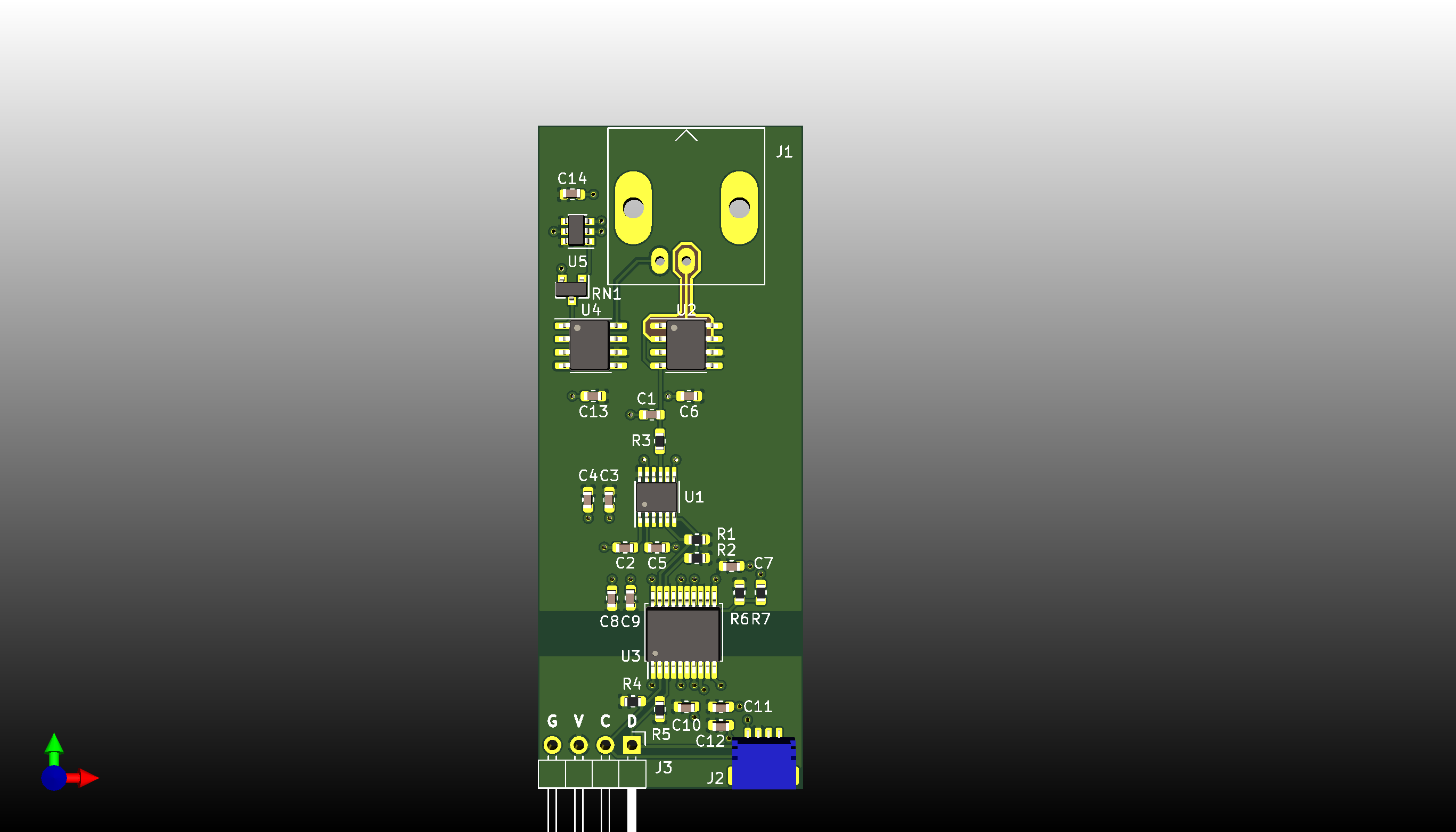
Long time lurker first time poster. I have questions regarding PCB guard rings in a pH meter circuit. I know that a typical combination pH electrode has really high output impedance so you want low leakage on the PCB as well as low input offset opamps. This first draft of the schematic and PCB has a guard ring surrounding the probe's output, but I don't have one surrounding the reference electrode input. I'm biasing that electrode with 512mV to make the signal unipolar.

So the main question is should I guard the reference electrode traces as well and if so, what potential should that guard trace be at? Also, just looking for considerations on the circuit as a whole. It's my first go with a pH meter. For reference, I'm only looking for 0.1pH resolution and 0.1pH accuracy. Temperature and pH range would be that of pool water.

In lieu of being able to post schematics, here's a link to the Github repo for the HW files repo

Circuit description: SOIC8 opamps U2 and U4 are LMP7721. Bias for the reference electrode is genereated by a MCP1501 1.024 reference and fed into a matched resistor divider (RN1). U1 is a LTC2471 ADC and U3 is a ADM3260 I2C isolator. R3 is 1k and C1 is 1uF. Decoupling caps on the LMP7721's are 0.1uF tantalums. C14 is a 2.2uF MLCC.

PCB top side 3d renderingPCB bottom side 3d rendering


@Kubahasn'tforgottenmonica

Just to make sure I was following your train of thought, is this what you had in mind:
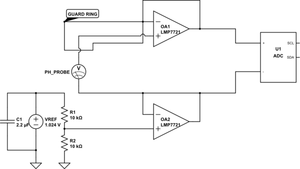
schematic

simulate this circuit – Schematic created using CircuitLab

\$\endgroup\$
5
  • 1
    \$\begingroup\$ Please post a picture of only the area of the amplifier (zoomed in) and showing top and bottom layers \$\endgroup\$
    – Voltage Spike
    Commented Jun 7, 2021 at 17:56
  • \$\begingroup\$ The absolutely best thing you can do is to raise the input pin off the PCB and route a floating wire to the center pin of a high quality collector - virgin Teflon insulator is a must. Everything else is a trade-off :) \$\endgroup\$ Commented Jun 7, 2021 at 18:16
  • 1
    \$\begingroup\$ The matched resistor network is an overkill from the perspective of accuracy, by the way: it doesn't matter what the voltage is, as long as it's far enough from the supply lines. Two 1% metal foil resistors will be plenty. The resistors themselves must be low-noise and metal foil is the best you can do AFAIK, but their ratio can be +/-20% and everything will still work OK as long as your ADC input is differential (it better be). \$\endgroup\$ Commented Jun 7, 2021 at 18:22
  • 1
    \$\begingroup\$ @Kubahasn'tforgottenMonica ADC input is single ended, which was why I used a matched resistor network - to get it as close to 512mV as possible. But, what you are saying makes sense. Go differential and feed in the bias voltage and it doesn't matter what the actual value is. I like that approach and the LTC2473 has differential inputs \$\endgroup\$
    – Andy
    Commented Jun 7, 2021 at 20:36
  • \$\begingroup\$ @Kubahasntforgottenmonica Just to make sure I was following your train of thought, is this what you had in mind: schematic \$\endgroup\$
    – Andy
    Commented Jun 7, 2021 at 23:56

1 Answer 1

6
\$\begingroup\$

This looks ok, one other thing to note is you if you want to prevent leakage beneath the input trace to the amplifier need a guard trace directly underneath it. The problem is FR4's impedance is something like 10^8 Ω (also depends on humidity) most opamps are much higher than that. So the current leaks out (or in) through the FR4. The guard trace keeps the voltage the same as the input trace, and when the voltage is the same no current flows through a resistor (FR4 is the resistor in this case)

I'd do this on the layer directly below the trace and tie it with a via or two to the guard ring.

enter image description here

I'm also having trouble seeing your gain resistor, it should have at least one terminal inside of the guard trace.

\$\endgroup\$
6
  • 3
    \$\begingroup\$ I'd explicitly add the driving principle behind your solution: you are considering the PCB material to be a weak bulk conductor, sort of like the black antistatic conductive foam. This requires a bit of an adjustment of the mental model for someone unused to thinking that way. It also informs any simulation efforts (mental or otherwise) in determining the best shape of the guard plane. \$\endgroup\$ Commented Jun 7, 2021 at 18:18
  • 1
    \$\begingroup\$ I guess it depends on how accurate you want need your input bias current and how much errror your application can tolerate. There are differences between a pA level amp or an fA level amp. to get pA's through fr4 you only need 100mV's on the other side. Anyway most pH meters have an impedance much greater than 10^8 so everything becomes a source of error (the two currents will add). \$\endgroup\$
    – Voltage Spike
    Commented Jun 7, 2021 at 18:25
  • 1
    \$\begingroup\$ I'm in full agreement - just trying to make it clear for those who might be used to treating FR-4 as an ideal insulator: with that mindset, your solution is pure magic, but as soon as you can see the virtual lattice of resistors formed by the FR4, it starts making sense :) \$\endgroup\$ Commented Jun 7, 2021 at 18:28
  • \$\begingroup\$ @VoltageSpike Amplifier is unity gain, so no resistors. I like your bottom side guard ring implementation. Thanks, I will use that. \$\endgroup\$
    – Andy
    Commented Jun 7, 2021 at 20:38
  • 1
    \$\begingroup\$ Only the input trace needs to be guarded, including the other trace will introduce a small amount of offset error from leakage current from that trace. \$\endgroup\$
    – Voltage Spike
    Commented Jun 7, 2021 at 20:44

Your Answer

By clicking “Post Your Answer”, you agree to our terms of service and acknowledge you have read our privacy policy.

Not the answer you're looking for? Browse other questions tagged or ask your own question.