0
\$\begingroup\$

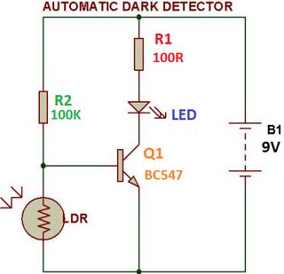
Here we have the typical “automatic dark detector” circuit:

automatic dark detector circuit

Let’s assume LDR=5Kohm with light, and LDR=2Mohm in darkness, the battery is 12V instead of 9V, and the transistor has a forward voltage Vbe=0.7V.

With light, per the voltage divider formula, we have Vbase=0.57V and the transistor is cut off.

In darkness, the formula gives Vbase=11.42V. Since this is much higher than 0.7V. Why does the transistor not burn?

\$\endgroup\$
15
  • \$\begingroup\$ That's not even a good topology for this. I would not even consider it. But to answer your question, you've forgotten the Thevenin impedance of the divider pair, haven't you? \$\endgroup\$
    – jonk
    Commented May 21, 2022 at 11:02
  • \$\begingroup\$ @jonk thank you very much for your comment. Yes, definitely I am missing something very basic :) I’m going to research the Thevenin impedance concept: youtu.be/xSRe_4TQbuo?t=656 \$\endgroup\$ Commented May 21, 2022 at 11:22
  • \$\begingroup\$ I don't think you included the base-emitter junction's impedance in your voltage divider equations. \$\endgroup\$
    – user16324
    Commented May 21, 2022 at 11:25
  • \$\begingroup\$ @user_1818839 That's usually pretty small. Ten or twenty Ohms. Or so. The emitter will have some, but usually less than one ohm. \$\endgroup\$
    – jonk
    Commented May 21, 2022 at 11:28
  • \$\begingroup\$ @jonk oops, edited comment. \$\endgroup\$
    – user16324
    Commented May 21, 2022 at 11:32

1 Answer 1

1
\$\begingroup\$

The resistor divider calculator only applies if the NPN's base-emitter doesn't clamp the voltage. However it does - so you can calculate that R2 runs 9-0.7 V, or 83 uA. The 2 MΩ LDR 'removes' 0.7/2M of that (0.35 uA), so basically all R2's current drives the NPN.

\$\endgroup\$
4
  • \$\begingroup\$ Thank you for your answer. Yes, intuitively I see that when the LDR is very high R2 dominates the circuit and current gets aplied to the base. But what I don’t get is why the base is at 0.7V. Why this holds? Is it a property of the BE “diode” or something like that? \$\endgroup\$ Commented May 21, 2022 at 13:10
  • \$\begingroup\$ I think the key word in your answer is “clamp” the voltage. What does it mean that the base-emitter clamps the voltage? Does it get “fixed” at 0.7V above earth? I’m sure this is all trivial stuff. Thank you all for your patience. Will try to understand better the case in which we only have a resistor and a diode in series. \$\endgroup\$ Commented May 21, 2022 at 13:29
  • \$\begingroup\$ Ok, I think it must be calculated simply using KVL. The voltage drop across the BE diode is 0.7V, so that’s the voltage at the base of the transistor. \$\endgroup\$ Commented May 21, 2022 at 14:02
  • \$\begingroup\$ Thank you for your time and answer jp312. \$\endgroup\$ Commented May 21, 2022 at 14:50

Your Answer

By clicking “Post Your Answer”, you agree to our terms of service and acknowledge you have read our privacy policy.

Not the answer you're looking for? Browse other questions tagged or ask your own question.