2
\$\begingroup\$

I have a resistive sensor that I'd like to use to generate an amplified voltage in a small range. I'd also like to shift/offset that range up and down with the use of a DAC to kind of "zoom in" to pre-defined regions during operation using an op-amp.

I should also note that the sensor does not inherently have any AC component and is not expected to change quickly (similar to a thermistor reacting to temperature changes).

I came up with this circuit to test: tested schematic
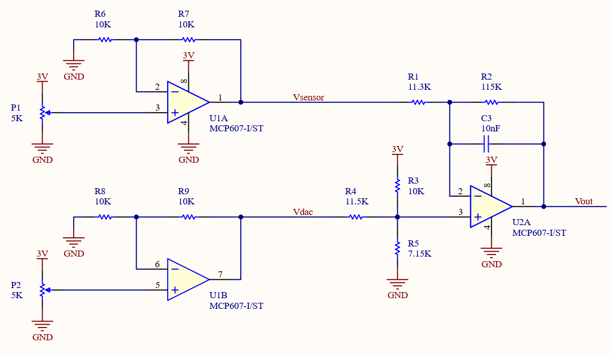
After some initial troubleshooting, I realized I was exceeding the upper input common-mode range of VDD–1.1V=1.9V which is why I added U1, R6, R7, R8, R9. This allowed me to measure ~0V to ~3V for "Vsensor" and "Vdac" and test "Vout" at specific ranges.

By solving the circuit, I derived the theoretical output voltage to be: \begin{align} V_{out} &= \frac{-R_2}{R_1}*V_{sensor} + \frac{R_5*(R_1+R_2)*(R_3*V_{DAC}+R_4*V_{cc})}{R_1*(R_3*R_4 + R_3*R_5 + R_4*R_5)} \end{align}

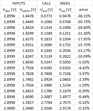
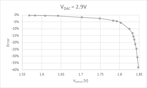
After running through several values of "Vsensor" between 1.57V and 1.85V for a constant "Vdac" of 2.9V, I noticed the error between the theoretical and actual "Vout" was poor - as bad -38%. I realize this is outside of the opamp linear spec, but an -18% error when Vout=0.15V seems too high when I expect it to be in the linear range.

Vout error chart Input/Output table

The MCP607 datasheet states the maximum input common mode voltage is 1.9V (for 3V supply) and I applied ~1.69V so I don't suspect that is the issue. It also states the output voltage is linear when it is at least 100mV away from the rails.

I tried adjusting the values of R3, R4, R5 so that the parallel resistance is close to R1||R2 with the thought that the input bias currents could be leading to additional input offset errors. Although the error was not improved, the sign was opposite (now Vsensor was 30% higher than expected).

I have tried again at Vdac set to 1.5V (worst error was -17%) and again at 0.1V (worst error was +11%). It seems the error is always the worst when Vsensor is highest and converges to 0% as Vsensor decreases.

I could use some help in troubleshooting. Any ideas what could cause this? Perhaps I'm not considering other key specs in the datasheet?

Thank you!

EDIT: I removed references to "difference amplifier" and instead called it op-amp

UPDATE: I tried removing the capacitor (C3), cleaning residual flux from pcb, and even removed U1 and connected PSU directly to "Vsensor" and "Vdac". Unfortunately, the error remained high at 25%. I input my values that I listed above into a PWL to simulate in LTspice and saw the worst error was ~2% and averaged ~0.6%. My search continues.

===============================================================

UPDATE: Rather than post my own answer and close this discussion, I decided to post an update to see what further contributions/improvements could be made. Furthermore, I still have more testing to determine if this behavior will be acceptable. Once that is complete, I will post an answer and close the discussion.

TLDR; By eliminating the trimpots and the amplifiers after them, I was able to reduce the error from ~30mV down to ~10mV.

After reviewing all the responses, I took a step back and tried to think through this again. To try and simplify the test setup as much as possible, I removed U1/R3/R5 and shorted R4. Then I connected alternate PSU channels directly as "Vsensor" and Vdac". I was happy to see that the measured "Vout" was within 3mV of the expected value throughout the range.

After further review, I believe part of my issue was with the trimpots themselves since I noticed them drifting a little over time. They are multi-turn ones but residual internal tension and disturbances while taking measurements may have caused the wiper to move slightly. The following 2x gain stage would only make it worse. Since I took my measurements one at a time with ~10s of averaging, there could've been enough time for things to change enough to be problematic.

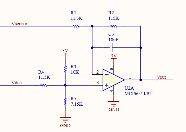
I eliminated the pots and U1, restored R3/R4/R5 back to the original values, and connected my PSU as the two inputs as follows: same as OP but without pots/U1 new sch without pots/U1
After testing multiple points in three ranges: results in table and chart formats The parts in green are meant to signify when "Vout" is in the linear range (at least 100mV away from the rails). results using PSU in table and chart forms
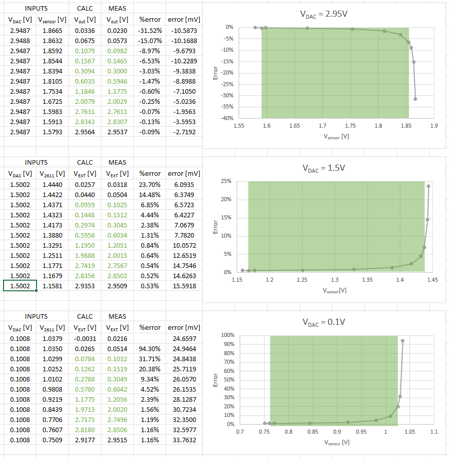
As @Jonk and @Spehro Pefhany mentioned above, the resistor tolerance also contributes errors. Moving forward, I'll look to incorporate a more stable reference voltage rather than base things off Vcc. I may also consider using 0.1% resistors.

Thank you, everyone, for your help!

As stated above, I will still test and look for further improvements and welcome any additional feedback that might arise. Once I complete my testing and am confident the issue has been resolved, I'll close the topic.

\$\endgroup\$
4
  • \$\begingroup\$ I thought I might add for your consideration what happens with 2% resistor values (I can compute it for other tolerances) are used for R3, R4, and R5. These are the results. Worth a quick thought in addition to everything else. \$\endgroup\$
    – jonk
    Commented Jul 18, 2022 at 20:26
  • \$\begingroup\$ did you use LTSpice or PSpice to simulate your circuit ? You will find the spice model here : microchip.com/en-us/product/MCP607, under "SPICE Model for MCP606/7/8/9 Devices" \$\endgroup\$ Commented Jul 18, 2022 at 20:38
  • \$\begingroup\$ @jonk Thanks, I'll look into this. \$\endgroup\$
    – Yodel185
    Commented Jul 19, 2022 at 12:56
  • 1
    \$\begingroup\$ @Arthur Chassande I appreciate the suggestion. I downloaded it and am playing with it now. It didn't work right away, but I found a work-around for the time being from here electronics.stackexchange.com/a/286441/318050 \$\endgroup\$
    – Yodel185
    Commented Jul 19, 2022 at 13:00

4 Answers 4

1
\$\begingroup\$

Unexpected non-linear response of \$\color{red}{\boxed{\text{difference amplifier}}}\$

This was the question title before the OP changed it 17 hours after my answer

and

I could use some help in troubleshooting. Any ideas what could cause this? Perhaps I'm not considering other key specs in the datasheet?

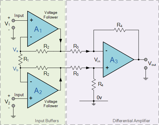
Your difference amplifier is badly designed. If you want to measure a difference accurately the resistors in the inverting limb need to have the same ratio as the resistors in the non-inverting limb. So in this image, R4/R3 is the same in both limbs: -

enter image description here

Image from here.

\$\endgroup\$
1
  • \$\begingroup\$ Although my circuit is meant to do some subtraction and amplification, I don't think "difference amplifier" was the right term for me to use. I updated my post above to reflect this. \$\endgroup\$
    – Yodel185
    Commented Jul 19, 2022 at 13:15
1
\$\begingroup\$

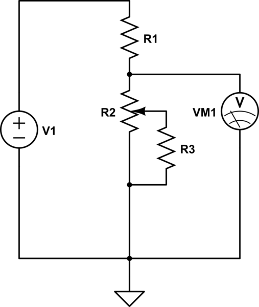
Just because the system is made of only linear components doesnt mean the response will be necessarily linear.Take this circuit for example:

schematic

simulate this circuit – Schematic created using CircuitLab

The output voltage will not be a linear function of the position of the potentiometer.

\$\endgroup\$
1
\$\begingroup\$

Your calculation of error as a percentage of voltage is more than a bit misleading (and nonlinear).

It's about -30mV for small outputs decreasing to about -9mV for outputs near the positive rail.

As a percentage of output range, then it's -1% to -0.3%. Pretty much what you'd expect with 1% resistors and without measuring the 3V offset reference (which has a bit more effect on the output than Vdac).

A 1% error in Vcc (2.99V rather than 3.00V) will more than account for the 30mV shift. Typically you'd want to use a very stable reference rather than the supply voltage, or get rid of it entirely since you have a DAC feeding the offset.

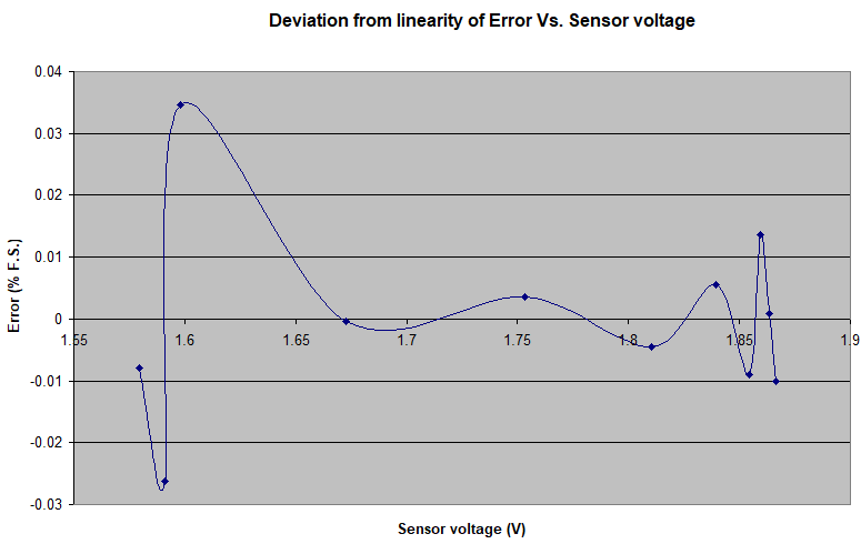
Since the original question was about linearity and you're still using the % reading .. based on the first group of additional data posted, here is the deviation from linearity of your error (from a least-squares fit). Seems to be well within +/-0.04% F.S.

enter image description here

\$\endgroup\$
2
  • \$\begingroup\$ I can see how the error calculated as a percentage is misleading. Doing this does exaggerate the problem which helps me find potential issues. The difference in voltages is small like you mentioned, so I am still looking to find a way to reduce it further. \$\endgroup\$
    – Yodel185
    Commented Jul 19, 2022 at 16:14
  • \$\begingroup\$ I suggest you measure the voltage at the non-inverting input of the op-amp U2A. That will help you figure things out. Also analyze the sensitivity of the output to each variable, resistor tolerance (and op-amp offset voltage). All small effects but when you are subtracting two numbers and multiplying by a large gain the errors get multiplied, even as a % of full scale. You can look at the error as an offset and a gain error, and deviations from that model will show you any nonlinearity. \$\endgroup\$ Commented Jul 19, 2022 at 16:22
0
\$\begingroup\$

U1A and U1B are configured for a gain of 2. They are trying to make a 6 V output while powered by a 3 V source. That will not work.

A conventional, non-rail-to-rail opamp needs around +/-2 V of headroom above and below the maximum signal excursions to meet published performance specs (older ones more, newer ones less). The signals at pins 1 and 7 have a max range from 0 V to +6 V, so the power rails would have to be +8 V and -2 V, not +3 V and 0 V.

The same applies to U2A, which looks like it has a forward gain of just over 10 for the Vsensor signal.

I'm not familiar with the MPC607, so its headroom req might be less. True R-R opamps have lower headroom requirements, but the power rails always must exceed the required signal swing, even if only by 0.1 V.

\$\endgroup\$
2
  • \$\begingroup\$ The MCP607 is a rail-to-rail op amp, so it only needs a few dozen mV of headroom. \$\endgroup\$
    – Hearth
    Commented Jul 19, 2022 at 15:22
  • \$\begingroup\$ I am not using the full range of the pots - only about half in this configuration due to the 2x gain. I mainly did this to easily adjust the voltages and the op-amp gives me a low output impedance. \$\endgroup\$
    – Yodel185
    Commented Jul 19, 2022 at 16:18

Your Answer

By clicking “Post Your Answer”, you agree to our terms of service and acknowledge you have read our privacy policy.

Not the answer you're looking for? Browse other questions tagged or ask your own question.