0
\$\begingroup\$

I have purchased a pH sensor board and it gives me an output in millivolts. I want to read this using an Arduino.

Usually this boards outputs from 400-1200 mV. When I use a multimeter, it gives me a reading of the output of the board.

Now when I connect the output of this board (which is giving me 400 mV output) to an Arduino analog input, the Arduino reads it as 3.3 V or something.

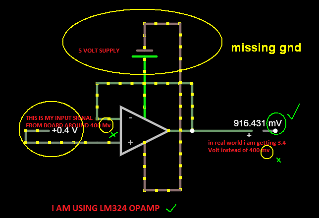
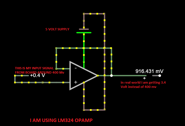
Then I thought it has to be an impedance issue. So I thought: let me put a unit buffer op-amp (LM324) inbetween and see if that works.

When I connect that 400 mV signal from the board to the unit-gain buffer op-amp, the op-amp gives 3.4 V as output (supply to op-amp is 5 V dc).

enter image description here

I don't understand why this is happening. Instead of giving me 400 mV it gives me 3.3 V. In this case the Arduino is out of the picture, as I am measuring the output of the op-amp with a multimeter.

I though there might be something wrong with my unit buffer op-amp, so what I did was: I used a voltage divider and generated 400 mV from it and supplied it to the op-amp.

In this case the op-amp did work as it should and gave me an output of 400 mV, so the op-amp is working properly. I used a battery here for the voltage divider supply.

I dont understand why the op-amp does not work as it should when I supply the output of my pH board.

Could you guys tell me what is issue here? I am not an expert in op-amps, but maybe current has some hand in this?

\$\endgroup\$
9
  • \$\begingroup\$ Have you connected the grounds of the two boards together? \$\endgroup\$ Commented Jul 26, 2022 at 11:00
  • \$\begingroup\$ yes , i did connected both ground and also without . when i connect ground of arduino with board ground. and measure output of board (which was 400 milivolt before connecting ground of two ) multimeter still gives me 3.3 volts. i dont get it why it turn 400 milivolt to 3.3 by just connecting ground. \$\endgroup\$ Commented Jul 26, 2022 at 11:07
  • \$\begingroup\$ Please show a diagram and describe how the op amp is powered. \$\endgroup\$ Commented Jul 26, 2022 at 12:06
  • \$\begingroup\$ here is circuit diagram dropbox.com/s/lxzzph1ql8c8bvz/… \$\endgroup\$ Commented Jul 26, 2022 at 12:27
  • 1
    \$\begingroup\$ ...a real-world diagram showing your sensor, opamp, power supply and arduino connections, with pin numbers (both arduino and opamp)... Sensor datasheet as well. \$\endgroup\$ Commented Jul 26, 2022 at 13:00

1 Answer 1

0
\$\begingroup\$

There are errors in simulation that may not match errors in realization. Ground by definition is 0V, locally.

Make real measurements to trace from input to output of Op Amp on every pin to find the faulty connection.

enter image description here

\$\endgroup\$

Your Answer

By clicking “Post Your Answer”, you agree to our terms of service and acknowledge you have read our privacy policy.

Not the answer you're looking for? Browse other questions tagged or ask your own question.