0
\$\begingroup\$

I want to design a circuit that takes as input two decimal digits binary coded as A1…4 and subtractionB1…4 and displays their , sum or (fulldifference using a two place BCD-to-7-segment display as selected by a signal C : A BCD adder)/subtractor.

I use full adder(s), (and), (xor) and (or) gates, Also I used input C carry in for subtraction, but the BCD circuit doesn't work like the way I want. When I use the A1 and B1 inputs, the result at the outputs will be incorrect . The other inputs work well. When I use carry, the subtraction of inputs, gives me an incorrect output value

The outputs can't be bigger than 15 in the process of additio,and cannot be negative in the subtraction process.

For example when I put 4+6 in inputs, the result of output will be 10. When I put 8+8, the result, the output will be 15. For some reasons the output cannot give me numbers bigger than 15.

In the process of subtractor, can't gives me negative numbers. For example, when I put 1-2 in inputs, the output will gives me 6.

enter image description here

\$\endgroup\$
10
  • \$\begingroup\$ Yes, I modified the circuit a little, but another problem appeared \$\endgroup\$ Commented Feb 8, 2023 at 13:59
  • \$\begingroup\$ If i put 4+5 in inputs, the outputs will be 9. But when i put 8+8 in inputs, than outputs will be 15. the outputs cannot gives me number bigger than 15 for some reasons. \$\endgroup\$ Commented Feb 8, 2023 at 14:23
  • \$\begingroup\$ yes i running my simulations. I can look my logic values on the wires when i put 7-segment \$\endgroup\$ Commented Feb 8, 2023 at 14:50
  • \$\begingroup\$ I didn't find the schematic better than this. I made this schematic from some website and youtube. i asked my teacher but he don't know what is the problem with this schematic. this is better schematic i can make now. \$\endgroup\$ Commented Feb 8, 2023 at 15:57
  • \$\begingroup\$ @toolic It appears that the page you quote has been removed. I get 404, \$\endgroup\$ Commented Feb 8, 2023 at 17:40

1 Answer 1

1
\$\begingroup\$

Your initial addition portion:

enter image description here

... is just fine. You've got that right. And it's standard practice. You should be able to see that the 5 bits exiting the output will obey the usual rules.

For example, in the case you mentioned, of 8 + 8, you should see that the carry out will be 1 while the remaining four bits are all 0. And in the other case you mentioned, 1 - 2, you should see the carry out is 0 and the other four bits are all 1.

That's what should happen in 4-bit binary.

But:

  1. A problem comes in when displaying a result. For example, if the carry out is 0 and you are subtracting, then the result is a negative value and you need to display a -, somehow. You need a way to show that the result is negative. I gather from your comments (not stated in the question) that you are thinking of just using an LED to indicate this.
  2. Another problem is that for subtraction where negative results occur, you need to convert that back to an absolute value -- which means complementing it back and adding 1 again -- in order to generate the lower digit needed to be displayed (with a minus sign, somehow.)
  3. A final problem comes during addition and when anything over the value of the value of 2*4+1=9 is generated. In this case, 2*3=6 must be added. (Since the lower bit is 0, this really means adding 3 to the middle 3 bits.) Suppose you have the output of 10 (01010.) Then to generate a BCD output you add 00110 to that: 01010 + 00110 = 10000. This gives the BCD result of 1 and 0 that you need to show 10 on the display. (Note that this operation has to occur whether the result is positive or negative, but that it must occur after step 2 has been dealt with and not beforehand.)

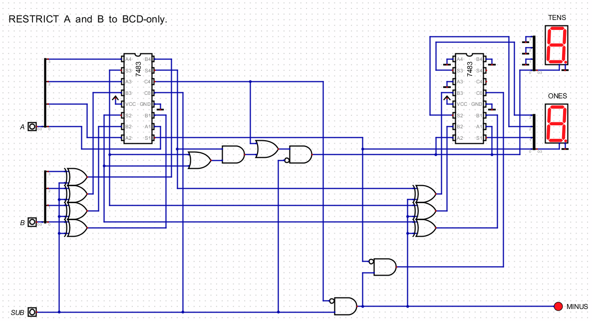
What's the plan to achieve the above?

Here's my thought. (Which also includes greybeard's note that I already know to expect a 1 in the tens display when I'm adding 3 in the 2nd 7483. So one less gate needed, now. Thanks!)

enter image description here

\$\endgroup\$
15
  • \$\begingroup\$ You already generate a signal decimal carry in addition: this is the LSB of the more significant digit, you don't need to recompute it from S1…4, saving at least the uppermost AND with one inverted input. \$\endgroup\$
    – greybeard
    Commented Feb 9, 2023 at 13:42
  • \$\begingroup\$ @greybeard Okay. Thanks. I think I see my folly. Yeah. If I'm adding 3 (6), then it must be because I expect to see a 1 in the tens digit. (I'm an idiot!) I'll make the adjustment. And thanks! \$\endgroup\$ Commented Feb 9, 2023 at 22:38
  • \$\begingroup\$ @greybeard I think the questioner is stuck with 7483s, whether mentally or by outside requirements. I've not used the 4000 series devices. (Too expensive, too few in variety, too difficult to find, and I never did lay hands on an RCA databook back when I was in my multi-board wire-wrapping days.) And thanks again for the kick in the head! \$\endgroup\$ Commented Feb 10, 2023 at 18:26
  • \$\begingroup\$ I tried your design, it can give me output 9 + 9 = 18, but for some reasons the output can't give me 17 and 1, and another problem if i put 0-8 it gave me -7, also it give me hexadecimal number in subtractor \$\endgroup\$ Commented Feb 11, 2023 at 23:25
  • \$\begingroup\$ @Mohammed Then you didn't get the right schematic. Here's the 0 - 8 = -8 example. You can see it works fine. And here's the 9+8 = 17 example. It also works fine. I've thoroughly checked it out. It works in every single case. I also automated the testing, as well. It's possible you may need to learn a little more about your simulator. \$\endgroup\$ Commented Feb 12, 2023 at 0:23

Your Answer

By clicking “Post Your Answer”, you agree to our terms of service and acknowledge you have read our privacy policy.

Not the answer you're looking for? Browse other questions tagged or ask your own question.