0
\$\begingroup\$

I have the following circuit as a transimpedance amplifier for ultrasound application: enter image description here
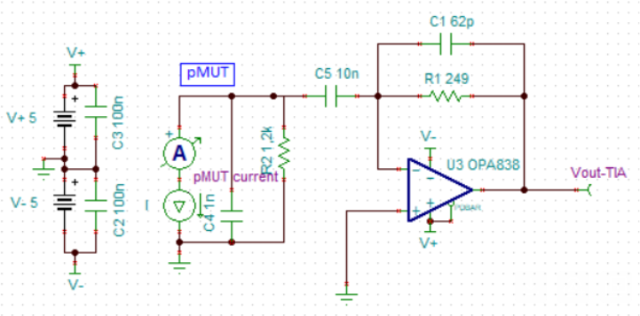
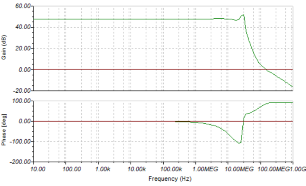
I checked all the possible criteria for the stability of the circuit, including phase margin, step response overshoot,....., and all of them confirm the circuit should be stable, following we see the diagram bode as well. As it is clear there is an picking in the bode diagram around 30MHz. enter image description here
I have 64 of this amplifier design on my PCB. I have used 5 decoupling capacitor for each Amplifier, two 100nF for +/- and two 2.2 uF for +/- and one 100 nF between positive and negative rail. When I apply +/-3 V to the circuit the PCB draws about 700mA current (e.g. 350mA form positive rail and 350mA from negative rail). In fact the circuit should consumes 64mA form positive rail and 64mA form negative rail based on the datasheet of the OPA838. Besides, I noticed all the Op-Amps are unstable and oscillates. But, when I reduce the supply voltage to +/- 1V everything is nominal and the current consumption is about 64mA from each rail and non of the Op-amps are unstable. Would you please let me know why is that? based on the datasheet the supply voltage can be +/-2.5V?!

Would you please let me know how can I make the circuit stable in +/-2.5V? and what is the root cause for this instability?

\$\endgroup\$
12
  • 1
    \$\begingroup\$ Are the sensors attached when performing these tests? The OPA838 is not unity gain stable, it needs the capacitance of the sensor to bring the loop gain to the point where it is stable. \$\endgroup\$ Commented Apr 2 at 8:14
  • \$\begingroup\$ Hello Kevin, thank you for the nice comment. No for my initial tests the sensor was not attached to the OPA838, do you think if I attached the sensor it will be stable even with +/- 2.5 V? \$\endgroup\$
    – Andromeda
    Commented Apr 2 at 9:02
  • \$\begingroup\$ If the sensor model is accurate and it does have 1nf of capacitance that should bring the loop gain to a stable point. For testing you could just replace the sensor with a 1nF capacitor. \$\endgroup\$ Commented Apr 2 at 9:08
  • \$\begingroup\$ @Kevin, thank you vey much for the guidance, so I will use a capacitor and let you the results, one pin of the 1nF cap with be tied to the inverting input of the OPA838, and the other pin will be tied to GND? right? \$\endgroup\$
    – Andromeda
    Commented Apr 2 at 9:16
  • \$\begingroup\$ As it is clear in the schematic as well, you can see that, there is a DC blocking Cap (10 nF) between the OPA838 and the sensor, do you think I can directly connect that Cap (10 nF) to ground for a quick test?? \$\endgroup\$
    – Andromeda
    Commented Apr 2 at 9:32

1 Answer 1

2
\$\begingroup\$

When I apply +/-3 V to the circuit the PCB draws about 700mA current

The data sheet says this: -

Single-supply operating range: 2.7 V to 5.4 V

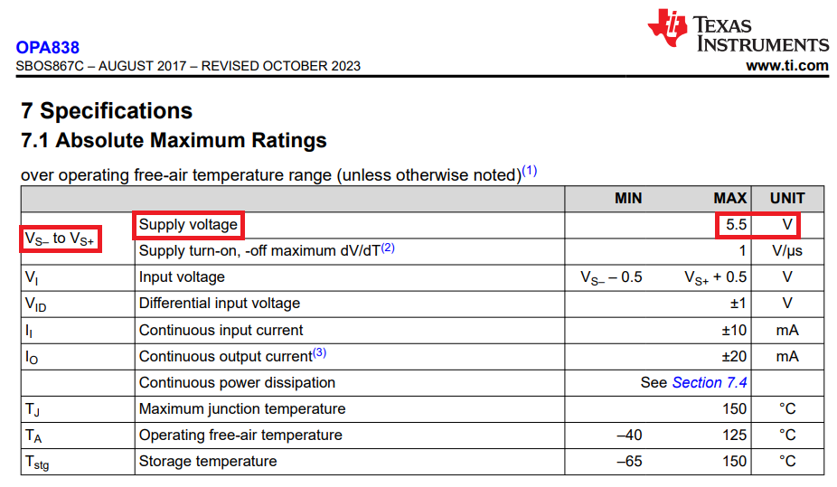
It also says this: -

enter image description here

So, there's a reasonable possibility that you have over-stressed the op-amps by applying 6 volts.

The data sheet also says this: -

Operating at the minimum recommended noninverting
gain of 6 V/V results in a 90-MHz, –3-dB bandwidth.

You may not be meeting this requirement in your design if C4 (1 nF) is actually lower than this. For instance, if C4 were as low as 372 pF then, you would be on the cusp of instability. Now, I can't tell whether C4 is something that is internal to the ultrasound transducer or not so, maybe you can clarify.

\$\endgroup\$
24
  • \$\begingroup\$ Thank you very much Andy for the helpful comment, already spotted this, and then decided to reduce the voltage, but I noticed it is only stable around +/-1V, should not it be stable also for +/- 2V as well? is the Op-amp now fully ON with +/- 1V? and do you think I don not have stability problem? \$\endgroup\$
    – Andromeda
    Commented Apr 2 at 8:31
  • \$\begingroup\$ Andy, regarding the C4 yes, it is the internal characteristics of the ultrasound transducer, and we have measured this value, which is around 1nF. But the issue is that even without connecting the transduces to the amplifier (nothing connected to non-inverting input), when we have supply voltage higher than +/1.3 V, the circuit is unstable. Please let me know if you need more data. \$\endgroup\$
    – Andromeda
    Commented Apr 2 at 8:47
  • \$\begingroup\$ @Behnam you must have the transducers connected else the gain becomes unity and the op-amp becomes completely unstable. The minimum gain is 6. C4 at 1 nF ensures that the minimum gain is around 16. \$\endgroup\$
    – Andy aka
    Commented Apr 2 at 8:56
  • \$\begingroup\$ Thank you for the nice guidance, yes, I will try this, so can we conclude like this? when there is no sensor connected to the OPA838 and the supply voltage is around +/- 1V, the OPA838 is not fully ON and do not oscillate (behave like it is stable), but when we increase the voltage higher than +/- 1.2 V, it is fully ON and needs the C4 to make the minimum gain of 6 to be stable? otherwise if the OPA838 is fully ON even with +/- 1V , it means, it is stable even without the C4!? \$\endgroup\$
    – Andromeda
    Commented Apr 2 at 9:11
  • \$\begingroup\$ Would you please let me know how can I calculate this: (The minimum gain is 6. C4 at 1 nF ensures that the minimum gain is around 16), I would like to know how this C4 make the minimum gain 16? what are the formula for this calculations? \$\endgroup\$
    – Andromeda
    Commented Apr 2 at 9:34

Your Answer

By clicking “Post Your Answer”, you agree to our terms of service and acknowledge you have read our privacy policy.

Not the answer you're looking for? Browse other questions tagged or ask your own question.