0
\$\begingroup\$

I 've implemented this basic logic gate on a breadboard. Only my circuit has +5 supply voltage. The resistor values are 10K for diode inputs and 1K for collector of the transistor. The transistor is a 2N3904 and the diodes are 1N4148.

Here's a pic:
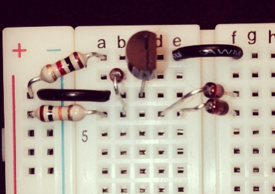
DTL

I'm really confused about the inputs for this. I've read that the inputs should be low voltage, but I've tried all sorts of voltages and nothing. However, when I put one of the inputs to ground, the LED turns on. This got me thinking, if in fact connecting input to ground was 1, then both of them being to ground "AND" would cause the LED to shut off. If thats the case, how on earth do I implement this with a button or switch? Also, is my circuit shorting somehow, or perhaps are these values not working with the +5V? I've tested the RTL version and the 1K + 10K + 2N3904 works perfectly.
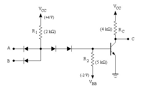

(source: jones at people.seas.harvard.edu)

\$\endgroup\$
2
  • \$\begingroup\$ You need to learn to understand how the circuit actually works and not work by "rote". This really really is a very easy circuit to inderstand once you grasp the basic principles. Omce you do you will be easily able to not only see how it works but to build other versions. Presumably "The LED" (unshown) is from collector to ground. || The transistor is turned on by current via R1 providing base drive., When Q1 (the transistor) is on then Q1_c is low and LED is off. If Da and Db float as whoen then R1 top is at 4V and current flows via R1, 2 series diodes (one on breadboard) to Q1_b .... \$\endgroup\$
    – Russell McMahon
    Commented Apr 28, 2015 at 7:49
  • \$\begingroup\$ .... so Q1 is on. | If either of Da or Db cathodes are grounded then R1 bottom is clamped to 1 diode dropabove ground and Q1_b gets no drive so Q1 is off so Q1C is pulled up[ by Rc (which is higher than usual at 4V for LED drive) and LED is on. IF you can understand how it works then all about it soon becomes (almost) obvious.|| Reverse Da and Db. Remove R1 and place it from Q1_b to ground (becoming R2 which you have not supplied). Add a resistor < R2 ) say 1K in series with 2 unnamed diodes . Now you have a gate with LED ON when inputs are low and OFF when either input is high. | Then ... \$\endgroup\$
    – Russell McMahon
    Commented Apr 28, 2015 at 7:56

1 Answer 1

1
\$\begingroup\$

That circuit looks like a NAND gate to me - Basically what happens is that if any of the inputs are driven low, it will pull down the voltage reverse biasing the pair of diodes meaning the transistor will be pulled down to zero by R2. If both of the inputs are high, the input diodes will not conduct and the transistor base will be pulled high through R1 causing it to switch on:

╔═══╦═══╦═════╦═══╗
║ A ║ B ║ Tr. ║ C ║
╠═══╬═══╬═════╬═══╣
║ 0 ║ 0 ║  0  ║ 1 ║
║ 0 ║ 1 ║  0  ║ 1 ║
║ 1 ║ 0 ║  0  ║ 1 ║
║ 1 ║ 1 ║  1  ║ 0 ║
╚═══╩═══╩═════╩═══╝

If the transistor is on, it will pull the output down to ground, hence the NAND function. Essentially the extra transistor acts as an inverter and hence you see the opposite polarity.

Interestingly if you invert both inputs what you will actually end up with is an OR gate, not an AND as you thought.


Edit 2

Based on the comments, it's now become clear why you were getting different results from what you expected. Basically the output is a current sink when low. As a result if you connect an LED from VCC to the transistor, the LED will be on when the output is low and off when the output is high. This is the case with any load wired in such a way, because only when the transistor is pulling down low is there any voltage across the load.

(Edit: I was right the first time, it's a NAND)

\$\endgroup\$
7
  • \$\begingroup\$ no - write is the wrong right, you didn't get what you wrote right (lol) but it looks like a NAND gate to me so +1 \$\endgroup\$ Commented Apr 28, 2015 at 13:48
  • \$\begingroup\$ @JImDearden Good catch! I'd gone with NAND first, then changed my mind and edited it to OR, then went back to NAND. \$\endgroup\$ Commented Apr 28, 2015 at 16:11
  • \$\begingroup\$ @TomCarpenter I know it's a NAND gate, I did a bad job asking the question. I really just want to understand how to power the inputs. Do I put them to ground? Do they get their own voltage source? \$\endgroup\$ Commented Apr 28, 2015 at 21:24
  • \$\begingroup\$ @JohnnyStarr you pull them down to ground to get a 0. Leave them floating or pull them up to VCC to get a 1. \$\endgroup\$ Commented Apr 28, 2015 at 21:29
  • \$\begingroup\$ @TomCarpenter hmm, something must be wrong with my circuit because I'm getting the opposite reaction. Leaving them floating keeps the LED on. When I tie either of them to ground the LED turns off. The cathodes of the input diodes are facing towards input too. That's partially why I posted a picture because it seems like my circuit is off. \$\endgroup\$ Commented Apr 28, 2015 at 21:32

Your Answer

By clicking “Post Your Answer”, you agree to our terms of service and acknowledge you have read our privacy policy.

Not the answer you're looking for? Browse other questions tagged or ask your own question.