0
\$\begingroup\$

I need to build a simple logic gate circuit such that when a single input signal or switch goes low it alternately activates one of three outputs as high. That is, every time it goes low the currently high output goes low and the next in the series goes high - cycling which output goes high between the three.

Years ago when I took an electronics class we used a program similar to CircuitLab. And I designed a very similar circuit. But I've lost that design and it was so long ago that I've gotten very rusty.

However, I can think of one way to build a circuit that would -almost- do what I want:

I could use a binary counter in combination with a 2-to-4 line single-bit decoder. (See the illustration on Wikipedia's decoder page.) The problem with that solution is it cycles between FOUR outputs. And my design requires that it cycles between only three.

As I said, I designed a circuit almost exactly like this years ago. And while the details are very foggy, I seem to recall that it was so simple that it only required one or more flip-flops (or latches) and a few other gates besides.

\$\endgroup\$

2 Answers 2

1
\$\begingroup\$

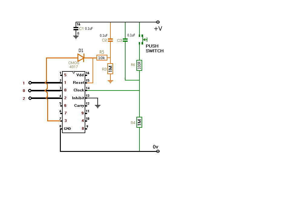
A simple circuit can be built using a 4017 counter.

enter image description here

The circuit normally counts 10 input pulses but by connecting the next output to the reset input via a small signal diode (eg. 1N4148) the 4th count resets the circuit to 0. It also allows you to expand the circuit very easily.to more outputs if required.

Edit (additional)

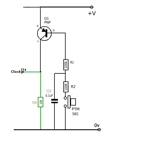
As OQ requires change when switch or signal input goes low then the clock input needs to be inverted. This can be easily accomplished with a single PNP transistor. A 100R resistor has been added in series with the switch to prevent it getting 'sticky' when discharging the capacitor (see Spehro's comment).

Also added the 10k between D1 and C2/R3 to the original circuit.

enter image description here

\$\endgroup\$
5
  • \$\begingroup\$ +1 This will work nicely because of two features the 4017 possesses- a Schmitt trigger clock input which allows an RC to debounce the clock, and the Johnson counter implementation that gives glitchless decoded outputs. I would add 10K from the 0.1uF/1M junction and maybe 100 ohms in series with the switch. The first so the output does not have to charge the 100nF capacitor, the second so the switch doesn't get sticky from welding due to the other 100nF cap. \$\endgroup\$ Commented Aug 10, 2014 at 12:29
  • \$\begingroup\$ Jim: The OP needs a low-going clock edge to change which output's hot, so the 4017 isn't a good fit unless you invert your positive-going clock input. \$\endgroup\$
    – EM Fields
    Commented Aug 10, 2014 at 12:48
  • \$\begingroup\$ @EMFields No. The reset input going high overrides the clock input. When Q3 goes HIGH it resets the counter to zero. Q0 goes HIGH and Q3 goes low (almost immediately). The 4017 is (IMHO) a good choice. see Spehro's comment \$\endgroup\$ Commented Aug 10, 2014 at 17:41
  • \$\begingroup\$ Jim: I apologize, you misunderstood me. The OP wants to advance the count when the switch - or the input signal - goes low, and you have it so the count is advanced when the switch or the input signal goes high. In order to fix it what you can do is tie pin 14 high, disconnect pin 13 from 0V, then connect the push switch from pin 13 to 0V and connect R4 from pin 13 to +V. You'll have to rework the debouncing, and it wouldn't hurt if you replaced the connection between D1-K U1-15 and R3 C2 with a diode series-opposed to D1. \$\endgroup\$
    – EM Fields
    Commented Aug 10, 2014 at 20:47
  • \$\begingroup\$ @EMFields My apologies also. I hadn't re-worked the original circuit to make it work with a low going switch. Will change and upload a modified circuit. \$\endgroup\$ Commented Aug 11, 2014 at 10:08
0
\$\begingroup\$

It's fairly straightforward. If you use a counter with an asynchronous reset, use the 4th decoder output to reset it. This will provide a very brief period when the counter is in the invalid 4th count. IF the counter has a synchronous reset or a synchronous load function, use the 3rd output of the decoder to assert that function (in the case of a synchronous load, load to zero). Then, when the counter output is 2 the next transition will be to zero.

Be aware that if you go the asynchronous route, you need to be aware of the possibility of skew errors in the decoder producing a false pulse long enough to reset the counter during one of the counter transitions other than the one you want. The asynchronous approach does not have this (potential) problem.

\$\endgroup\$

Your Answer

By clicking “Post Your Answer”, you agree to our terms of service and acknowledge you have read our privacy policy.

Not the answer you're looking for? Browse other questions tagged or ask your own question.