1
\$\begingroup\$

I have had EMI problems in the past and I have decided to implement clock distribution with termination.

I have a 25 MHz crystal that travels through a 50 \$\Omega\$ strip in the PCB and splits into two. After the split the strips have an impedance of 100 \$\Omega\$. Each strip goes to an IC and then is terminated with a 100 \$\Omega\$ resistor to ground. I copied the idea from a book. (High speed digital design. A handbook of black magic) enter image description here
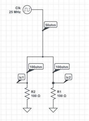
When I turn on the board, I noticed the ICs don't operate well as they miss clocks. When I remove the terminating resistors all is ok. I am trying to do a good job to prevent problems with EMI.

What am I missing?

\$\endgroup\$
6
  • \$\begingroup\$ What impedance do the \$\text{Ic}_k\$ present? \$\endgroup\$
    – copper.hat
    Commented Nov 29, 2014 at 4:55
  • \$\begingroup\$ And what load is the source designed to drive? \$\endgroup\$
    – The Photon
    Commented Nov 29, 2014 at 5:02
  • \$\begingroup\$ @ThePhoton the oscillator drives an stm32 and an altera device. Stm32 doesn't have impedance data but it says input capacitance is 5pf. I am sure same for altera. I don't have the data sheet of the oscillator readily available. Need to go to work to dig that out. \$\endgroup\$
    – TGG
    Commented Nov 29, 2014 at 5:14
  • \$\begingroup\$ An emu is a large flightless bird found in Australia. Did you mean EMC or EMI? \$\endgroup\$ Commented Nov 29, 2014 at 5:16
  • \$\begingroup\$ I am assuming when you said the source is a "crystal" you actually mean it is a crystal oscillator. A crystal by itself won't oscillate without some support circuitry. \$\endgroup\$
    – The Photon
    Commented Nov 29, 2014 at 5:30

2 Answers 2

3
\$\begingroup\$

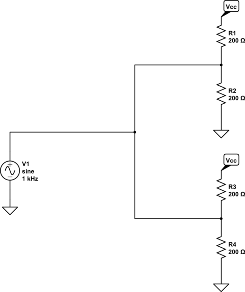
It sounds like your oscillator is designed to drive a CMOS load. With the load you gave it, it has to produce 66 or 100 mA to reach a high voltage (66 mA for 3.3 V, 100 mA for 5 V), and it's probably not designed to do that.

One option is to terminate with the equivalent of 100 ohms to Vcc/2:

schematic

simulate this circuit – Schematic created using CircuitLab

This reduces the output current required from the source by half.

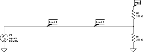
Even better, if you're able to do it, is route the signal past the two loads in sequence and terminate only once. Since you're able to produce 100 ohm tracks, use that geometry for the whole path:

schematic

simulate this circuit

This reduces the current demanded from the source by half again.

Of course it's also possible to add a buffer amplifier that can drive the relatively low impedance of your load, but that adds components you might not have budget or space for.

\$\endgroup\$
4
  • \$\begingroup\$ You are right. 33mA for each node. This is probably the culprit. Power consumption is a problem and I rather spend a few mA at most. Sounds like I am on the wrong track to optimize the power and the emi. What other topology you would recommend? \$\endgroup\$
    – TGG
    Commented Nov 29, 2014 at 5:35
  • \$\begingroup\$ At 25 MHz you can probably get away with not terminating anything. The closer you can place the oscillator and the two loads to each other, the more likely that is to work. If you get them within, say, 10 cm of each other you're not likely to have a problem. Maybe leave a location for a 5-10 ohm series resistor at the oscillator output to help slow down the rise and fall times and reduce emissions (but stuff it with 0 ohms to get started). \$\endgroup\$
    – The Photon
    Commented Nov 29, 2014 at 5:40
  • \$\begingroup\$ Before I failed the EMI with no termination and end up using spread spectrum oscillator to pass EMI. This design I cannot use spread spectrum. I didn't try the series resistor though. If I don't use termination, shall I control the impedance? \$\endgroup\$
    – TGG
    Commented Nov 29, 2014 at 5:43
  • \$\begingroup\$ Unfortunately there isn't really any matched impedance solution that doesn't end up burning more power, AFAIK. You could try an RC termination (100 ohms with a series capacitor to ground). That would eliminate the static current through the termination. \$\endgroup\$
    – The Photon
    Commented Nov 29, 2014 at 6:00
2
\$\begingroup\$

This is too late, of course, since you've already awarded points, but The Photon is mistaken. You can do what you want without the power loss entailed by termination.

The technique you want is called series termination. This is (sort of) The Photon's technique minus the capacitor. At the output of the oscillator you put a 50 ohm resistor to match the 50 ohms associated with the trace. You then remove all your other termination resistors.

See, for instance, http://www.ti.com/lit/an/scaa045a/scaa045a.pdf page 5.

It is not appropriate for driving low impedance loads, since the voltage divider effect produced by the series and load resistors will reduce the signal amplitude at the load(s). Assuming you're using CMOS or FET loads, this will not be a problem, since the load resistance is high compared to the transmission line impedance. And, of course, since the load resistance is high, the power dissipated in the series resistor is also low.

\$\endgroup\$
1
  • 1
    \$\begingroup\$ Series termination also doesn't work when the signal path is branched as in OP's circuit. It could work if he can rearrange the loads along an unbranched path. \$\endgroup\$
    – The Photon
    Commented Nov 29, 2014 at 16:48

Your Answer

By clicking “Post Your Answer”, you agree to our terms of service and acknowledge you have read our privacy policy.

Not the answer you're looking for? Browse other questions tagged or ask your own question.