4
\$\begingroup\$

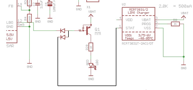
I am recreating the Adafruit Powerboost 500c Circuit, but I want to reduce the LED's I need down to one. It has four LED's to represent the following signals, next to which I put the desired behavior for my circuit:

  • BLUE - Power (I don't care about this signal)
  • RED - Low Battery - The LED should be lit when the battery is Low.
  • ORANGE - Charging - The LED should be lit when the battery is charging.
  • GREEN - Fully Charged - The LED should be unlit when the battery is charged.

I am removing the BLUE LED and R5. I am removing the GREEN LED and R7. I want to light a single LED if either the input to the RED LED or the input to the ORANGE LED is high. I wasn't sure if just hooking both inputs to an LED without other circuitry was a good idea so I googled "OR Gate circuit" and discovered three possibilities: a Diode OR Gate, a transistor OR Gate, and an OR Gate IC. If any of these is the best choice, which is it and why? If none is best, then what is?

Note: I asked this question before in an attempt to ask in a "generic as to be helpful to others" way and I was told that I needed to provide more details (among other comments on my poor circuit design that, while helpful, didn't answer my question). I provide more details and the thread was too old to warrant attention and, consquently, I did not get the answer I was looking for. I would delete my old question if I could, as I clearly presented it poorly.

\$\endgroup\$
3
  • \$\begingroup\$ I think a diode-'OR' should work when you insert one diode at base side of Q1 and connect the other diode to U2/STAT. Do be aware of diode polarity, because of the inverted inputs and the inverting transistor. \$\endgroup\$
    – jippie
    Commented Jan 9, 2015 at 6:08
  • \$\begingroup\$ Why would you ever want fewer LEDs? \$\endgroup\$ Commented Jan 9, 2015 at 6:32
  • \$\begingroup\$ LED's are great but if you have four lights for charging, one for wifi, one for bluetooth, ... it gets a little difficult to keep track. Just google Nintendo 3DS LED colors and you will see some jokes/complaints about a similar issue. That aside, most mobile devices only have one power LED, sometimes it is multi-color, but there is usually only one LED. \$\endgroup\$
    – Nate
    Commented Jan 9, 2015 at 20:53

1 Answer 1

4
\$\begingroup\$

A diode OR using 2 diodes as shown will work.
Either drive line can pull Q1 base low without affecting the other.

Technically it's a diode AND with +ve logic but as our activating signals are active-low i't a diode OR with negative logic.
It could also be seen as a DTL = "Diode transistor logic" AND (or OR) gate.
Long ago you could buy AND gate ICs and this is almost exactly what was inside.
So all your choices are ~~~~~~= the same :-).

This is "best" because it works, is quick and easy and only requires 2 diodes.
Diodes can be about anything.
Usual small diode is 1N4148 but a 1N400x or almost anything else will work.

In1 / In2 / Out

0 0 0
0 1 0
1 0 0
1 1 1

enter image description here

\$\endgroup\$
0

Your Answer

By clicking “Post Your Answer”, you agree to our terms of service and acknowledge you have read our privacy policy.

Not the answer you're looking for? Browse other questions tagged or ask your own question.