0
\$\begingroup\$

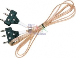
I'm working on a test box for fencing body cords. These cords are always 3 wires, and will plug into a box that I'm still designing. The test box I currently use connects to a multimeter and has a switch to change from line to line to test each individually. I'd like to build a circuit that can test all three simultaneously using an Arduino. So far, I've been able to use a set of voltage dividers in parallel to measure the resistances, however in the case that one of the plugs has been mis-wired (A wired to B pin, etc) this circuit will not know the difference. Is there any way to isolate each of the circuits, so that I both know that pin A is wired to pin A (B to B, C to C) and can also measure the resistance across the wire?

For reference, here's the current bread board layout that I'm playing with (as well as some code that I've borrowed for making an Arduino ohmmeter) http://123d.circuits.io/circuits/755318-basic-fencing-wire-test-box/embed#breadboard The three resistors near the top are the 3 I'm interested in testing.

\$\endgroup\$
3
  • 2
    \$\begingroup\$ What is the expected resistance range for the 3 wires, and what is the nominal "fail" level? \$\endgroup\$ Commented Apr 27, 2015 at 20:43
  • \$\begingroup\$ Anything over 1 ohm on a line would be a technical failure, although we do allow some variance up to 2-3 ohms. \$\endgroup\$ Commented Apr 28, 2015 at 2:00
  • \$\begingroup\$ Please post schematic. Breadboard wiring diagram doesn't count as a schematic. Folks here will not strain to reverse the schematic from the breadboard. \$\endgroup\$ Commented Apr 28, 2015 at 2:22

2 Answers 2

0
\$\begingroup\$

Firstly, does it really need to measure resistance? As far as I can tell, it will be a case of a contact either being open circuit or short circuit - nothing inbetween?

The advantage of microcontrollers, Arduinos and so on is they can perform operations in very quick succession, such that they appear simultaneous to the human eye.

So make the Arduino test one part at a time, in quick succession. Thus it will appear as if it has tested all 3 simultaneously.

I cannot work out what your fencing body "cord" does exactly. If you give more information on how it works, perhaps someone can design the circuit for you.

Also, what you say about the mis-wiring problem is not clear: do you want the circuit to some how know if you have mis-wired it? I can't see that being possible.

Edit:

I think I know roughly what you want now. At the least, I can give you a circuit which you can adapt.

The principle will be as per Spehro Pefhany's comment: use 6 pins from the Arduino- three digital to drive and three analog to read. So this is how that would look:
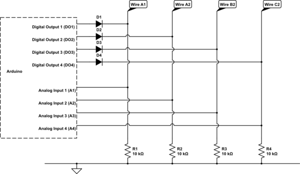
schematic

simulate this circuit – Schematic created using CircuitLab

Ok, it looks like CircuitLab is giving me errors. I will come back to that circuit when it's back up. In the meantime, this is how your pseudocode for the above would look:

  1. Set digital outputs DO1,DO2,DO3 as 1,0,0,0
  2. Now read Analogue input A2.
  3. If Analog input A2 is high, then both A wires are connected. Higher value = lower resistance between wires A and other A.
  4. Now read Analogue input A3.
  5. If Analog input A3 is high, then wires A and B are connected. Higher value = lower resistance between wires A and B.
  6. Now read Analogue input A4.
  7. If Analog input A4 is high, then wires A and C are connected. Higher value = lower resistance between wires A and C.
  8. Set digital outputs DO1,DO2,DO3, D04 as 0,0,1,0
  9. Now read Analogue input A4.
  10. If Analog input A4 is high, then wires B and C are connected. Higher value = lower resistance between wires B and C.

The above will firstly allow you to confirm that the plug is connected the right way. (If the first A is connected to the other A). Then it will let you measure the resistance between all three wires. If you want, you could expand the above to test between all three wires on both ends. The above circuit has some redundancy, you might have noticed. With the above pseudocode, you wouldn't need DO4, D4, R1, A1. So if for example you wanted to test resistane/continuity between 6 wires, you would just need 5 digital ouputs, 5 digital inputs, 5 resistors and 5 diodes.

So you do not need to read the resistances simultaneously. Steps 1-8 above can be completed within a very tiny fraction of a second - in the order of 100 microseconds. (one ten-thousandth of a second).

\$\endgroup\$
5
  • \$\begingroup\$ There are regulated limits to what the resistance of "open" and "short" circuit are. I haven't played with such weapons for years but given they are physical devices being beaten to a pulp by the user, there is always the possibility of an indeterminate state. Likewise with the wiring .. there is always the possibility of the body cord (sits between the weapon and the spool connector) being incorrectly repaired. \$\endgroup\$
    – Peter M
    Commented Apr 27, 2015 at 20:52
  • \$\begingroup\$ Ok, but it would still just need to know whether the resistance is higher or lower than a given threshold? \$\endgroup\$
    – Jayy
    Commented Apr 27, 2015 at 21:03
  • \$\begingroup\$ I can't remember the exact details, but there would be an upper and lower threshold depending on the contact switch state. \$\endgroup\$
    – Peter M
    Commented Apr 27, 2015 at 21:11
  • \$\begingroup\$ Resistance is the most important part to measure here, each of the lines needs to be <1 ohm, although we can allow slightly more to pass when checking them. I did consider testing one line at a time quickly, but I'm not sure what that would actually look like. Pseudo-code wise, I'd like to see something like this: 1)Power to A 2)Test Resistance to other A and report value 3)Confirm no continuity to B 4)Confirm no continuity to C 5) (repeat for B and C) If there is a way to do that set of steps quickly and accurately then I would be golden. \$\endgroup\$ Commented Apr 28, 2015 at 2:02
  • \$\begingroup\$ What is the purpose of the diodes in this circuit? I'll have to order some from somewhere. \$\endgroup\$ Commented Apr 28, 2015 at 12:16
0
\$\begingroup\$

It appears that it is simply a specialized cord you're talking about testing- a 3-wire cord with two polarized male plugs, one at each end:

http://www.fencepbt.com/pbthome3.nsf/568E049DDF6860CF852573F800123C2C/$File/body-cord-epee-thumb.jpg

To thoroughly test this you must look for opens and shorts between any combination of pins.

One way to do this is to plug the cable into two suitable female connectors attached to your micro and actively drive each of the pins high or (through a resistor such as 1K) and connect the other end through a resistor (such as 10K) to ground, and read each value using the ADC. The pins not driven high should be left high-impedance (you'll get a full value for a short) if you drive them low actively you'll get half value at more than one pin for a short.

You might drive just one high and a time, and check the values at each of the other three. If more than one goes high, then there is a short. If the wrong one goes high, there is a mis-wired connection. If none goes high then there is an open connection or wire.

You can run through these three tests very quickly, over and over again, and make a decision at the end of each set of tests what the status of the cable is. You might allow something like 20ms for each test, so the verdict would be handed down at 16Hz or so. That would allow you to wiggle the cable with the tester operating, which would help diagnose intermittents.

If you actually want to measure the resistance, as opposed to looking for continuity, you will probably have to put a relatively high current through the wire and amplify the signal at the other end with something like a few op-amps, so a handful of additional parts.

\$\endgroup\$
3
  • \$\begingroup\$ Of course there is also this style: leonpaulusa.com/acatalog/Bayonet_Bodycord.html, but that just changes the connector. (The pic you showed is for one particular weapon type.) \$\endgroup\$
    – Peter M
    Commented Apr 27, 2015 at 21:27
  • \$\begingroup\$ The box I'm building already has the connectors for the different body cord ends, but the idea is basically the same regardless. I think the ultimate solution is to find a way to test each line separately in some sort of loop. I'm not sure how to switch the voltage between the three pins though. \$\endgroup\$ Commented Apr 28, 2015 at 2:08
  • 1
    \$\begingroup\$ Use 6 pins from the Arduino- three digital to drive and three analog to read. \$\endgroup\$ Commented Apr 28, 2015 at 3:05

Your Answer

By clicking “Post Your Answer”, you agree to our terms of service and acknowledge you have read our privacy policy.

Not the answer you're looking for? Browse other questions tagged or ask your own question.