2
\$\begingroup\$

I am using an LDR on an Arduino Pro Mini with an analog interrupt. The Arduino goes to deep sleep when there is no light or it's not busy:

Sleepy::powerDown();

The interrupt on the LDR looks like this:

PCintPort::attachInterrupt(lightPin, wakeUp, CHANGE); // lightpin = A0

This works great, not too fast. But the problem I'm having is that this only works with great increments in light, not with small increments. In fact, nothing happens when the LDR gives a little less resistance.

Is this due to the kind of sleep mode? Maybe because of some kind of insensitivity? Is there a hard-coded threshold? I'm not that experienced with electronics or microprocessors. Am I missing something?

Waking up the Arduino when a small change in light occurs is critical for my application. I can't keep the Arduino constantly awake because it runs on a battery.

If you guys need anything more, like my full code, just say so! Thanks.

\$\endgroup\$
4
  • \$\begingroup\$ You can still sleep for >90% of the time if your Arduino wakes up ten times a second, samples an analogue input, compares to previous readings and then sleeps again. This way you can also do fancy things to reduce noise like integrating over time. \$\endgroup\$
    – David
    Commented May 15, 2015 at 16:01
  • \$\begingroup\$ That is true. Though, I want to sleep all the time and only wake up when there is a little change (that could be less than once a day). \$\endgroup\$ Commented May 15, 2015 at 16:15
  • \$\begingroup\$ You'll probably find that waking up 10 times a second for a few cycles won't drain the battery before the end of its usable life. You might be surprised if you do the math. \$\endgroup\$
    – David
    Commented May 15, 2015 at 16:18
  • \$\begingroup\$ Remember that leaving any kind of subsystem active (e.g. interrupt on change) will use battery power at all times, even during sleep. You can't escape this, only minimise it. \$\endgroup\$
    – David
    Commented May 15, 2015 at 16:28

3 Answers 3

2
\$\begingroup\$

An LDR is an analogue device. Its resistance varies, and some devices in the dark have a 1 megohm resistance, for others it can be 20 megohm. In light, it can be as low as 150 kilohm.

Interrupt pins on microprocessors are digital inputs, and they are either at 5 volts or 0 volts.(typical logic levels). They don't have in-between values.

Have you got the LDR connected to an analogue or digital input? I'm guessing digital, because you mention "interrupt".

The problem you've got is you have to convert a change in resistance (which results in a change in voltage or current) into a digital output of 5 volts or 0 volts and feed into the digital interrupt pin.

If you connect the LDR to an analogue input then you actually measure the brightness of light, and you'll get a digital code output from the ADC (analogue to digital converter) which will represent the brightness of light falling on the LDR. Then you can code up what threshold you like and decide what you want to do with the integer number which represents the brightness of light falling on the LDR.

If want to connect the LDR to a digital input, then you are going to have to have some way of converting from a continuously variable analogue value (voltage, current) into a digital logic level (5 V or 0 V) to feed into the digital pin on the Arduino. You are going to need some kind of threshold detection.

You are going to have to decide what resistance change on the LDR causes the digital pin on the processor to change from a logic value of 0 to logical value of 1. May be you have to experiment with the LDR and measure the resistance at different levels of illumination.

Then you can build a circuit to give you a logic level output when the light level changes in the way you want. Look up comparator circuits, or even "CMOS voltage comparators". These take in an analogue voltage, and you set a threshold hold voltage. You'll need a couple of resistors configured as a 'potential divider' to set the threshold voltage to the comparator chip, possibly even a trimmer potentiometer to enable it to be adjustable.

There's a little bit of work involved; you'll have to calculate resistance values.

So I think the first thing you need to think about is whether you really want just a digital output (1 or 0) in response to a change in light level or whether you want to measure the light level and feed the LDR signal into an analogue input and obtain a number representing the brightness level, that is, do you want to feed the LDR into a digital input (interrupt?) line or have the LDR feed into an analogue to digital converter?

Given that you want the Arduino to wake up, then I think you're really looking to output a digital logic-level compatible output from the LDR circuit, which means you need to detect the brightness of light crossing a threshold. So you want to be looking up "CMOS voltage comparators". I don't know what the logic inputs are for the Arduino, so a CMOS output comparator may not be suitable, but go have a look at them. If you look at "voltage comparators" you'll come across circuits using operational amplifiers, worth looking at so you can gain an understanding of how they work and how to set the threshold value using resistors, but you really want to be looking for voltage comparators which have a logic-compatible output (5 V, 0 V = logic 1 or logic 0). These are better suited to what you need.

\$\endgroup\$
5
  • \$\begingroup\$ Thanks for the very explaining answer. I do want to measure the light, I do have the LDR connected to an analogue pin (A0, see code for interrupt attachment). What I want is to know when, lets speak figuratively, the resistance goes from 10 kOhms to 9 kOhms. I don't know if that is much or not, but the Arduino had to be woken up every time the light changes slightly. \$\endgroup\$ Commented May 15, 2015 at 16:11
  • \$\begingroup\$ I must admit I don't know that much about the Arduino's. Do they have an interrupt facility based on the output of the ADC (analogue to digital converter)? In theory it's possible but I've never seen it in a microcontroller before. You're going to have to calculate what the change in voltage at the input to the DAC is for 1KOhm change in resistance of the LDR.(from say 9K to 10Kohm). Then when you have the voltage change you can calculate what the change in binary output code of the ADC will be. \$\endgroup\$
    – Dean
    Commented May 15, 2015 at 16:18
  • \$\begingroup\$ I'm not that familiar too, but what I know is that the Arduino does wake up when I shine a flashlight on the LDR. That could be because of the built in ADC passing a threshold when the LOW input measurement of the (converted) digital value changes to HIGH. In that case the interrupt strategy may be a dead end. \$\endgroup\$ Commented May 15, 2015 at 16:25
  • \$\begingroup\$ The ADC might have an input range of 0-5 volts and be a 14 bit ADC,. 2^14 = 16384 possible levels. 5 volts divided by 16384 = 305 microvolts per level. This assumes everything is linear. So with a 9K value of resistance on the LDR you, calculate the voltage input to the ADC and you can then calculate the binary code read from it by the processor. Then do the same again for a 10Kohm resistance on the LDR. So can you calcuate the actual digital values read from the ADC. \$\endgroup\$
    – Dean
    Commented May 15, 2015 at 16:26
  • \$\begingroup\$ It's getting a bit more complicated, but if the arduino has a built in DAC too, you could output on the DAC a software adjustable voltage, and use that voltage to set the threshold of a comparator circuit which triggers an interrupt pin. In this way, you can define in software what voltage (what level of illumination) triggers an interrupt to the processor. But I fear what you really want to do is have the processor in sleep mode for most of the time but I don't think the DAC will keep its set output voltage in sleep mode? Worth checking. \$\endgroup\$
    – Dean
    Commented May 15, 2015 at 16:28
0
\$\begingroup\$

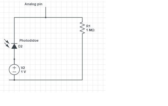
As I understand your point of view you want the interrupt function to be activated everytime light is on despite its weak power.Even a small amount of light should set your lightPin from low to high.

In that case I might wonder whether a photodiode is a appropriate solition for you. However you have to watch out selecting the right photodiode considering your light source (see a possible circuit). To enforce the signal you might even make use of opAmp. enter image description here

Other than that if you really want to stick to an LDR I agree with Dean's points. However be sure that you have chosen the correct LDR for your light source. Even the resistance of the LDR must be considered.

\$\endgroup\$
0
\$\begingroup\$

Is this due to the kind of sleep mode?

it is due to the gpio mode and input pin structure. for the code to work, the pin is configured as gpio. Being a ST pin, its logic changes will need to meet a fairly high threshold (to go high) or low threshold (to go low).

The typical solution is to put a comparator on that, either outboard or inboard, that will trigger a logic high or low based on the light divider's voltage output. for the inboard solution, you will need to check to see if the comparator works in sleep and if its interrupt can wake up the mcu.

Another approach is to use the adc: wake up the mcu periodically, take a reading of the ldr, test its value and act on that, then go back to sleep.

a better solution is to find a mcu with windowed adc.

\$\endgroup\$

Your Answer

By clicking “Post Your Answer”, you agree to our terms of service and acknowledge you have read our privacy policy.

Not the answer you're looking for? Browse other questions tagged or ask your own question.