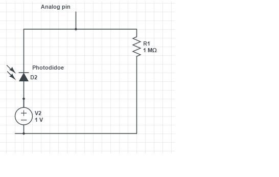
An LDR is an analogue device. Its resistance varies, and some devices in the dark have a 1 megohm resistance, for others it can be 20 megohm. In light, it can be as low as 150 kilohm.
Interrupt pins on microprocessors are digital inputs, and they are either at 5 volts or 0 volts.(typical logic levels). They don't have in-between values.
Have you got the LDR connected to an analogue or digital input? I'm guessing digital, because you mention "interrupt".
The problem you've got is you have to convert a change in resistance (which results in a change in voltage or current) into a digital output of 5 volts or 0 volts and feed into the digital interrupt pin.
If you connect the LDR to an analogue input then you actually measure the brightness of light, and you'll get a digital code output from the ADC (analogue to digital converter) which will represent the brightness of light falling on the LDR. Then you can code up what threshold you like and decide what you want to do with the integer number which represents the brightness of light falling on the LDR.
If want to connect the LDR to a digital input, then you are going to have to have some way of converting from a continuously variable analogue value (voltage, current) into a digital logic level (5 V or 0 V) to feed into the digital pin on the Arduino. You are going to need some kind of threshold detection.
You are going to have to decide what resistance change on the LDR causes the digital pin on the processor to change from a logic value of 0 to logical value of 1. May be you have to experiment with the LDR and measure the resistance at different levels of illumination.
Then you can build a circuit to give you a logic level output when the light level changes in the way you want. Look up comparator circuits, or even "CMOS voltage comparators". These take in an analogue voltage, and you set a threshold hold voltage. You'll need a couple of resistors configured as a 'potential divider' to set the threshold voltage to the comparator chip, possibly even a trimmer potentiometer to enable it to be adjustable.
There's a little bit of work involved; you'll have to calculate resistance values.
So I think the first thing you need to think about is whether you really want just a digital output (1 or 0) in response to a change in light level or whether you want to measure the light level and feed the LDR signal into an analogue input and obtain a number representing the brightness level, that is, do you want to feed the LDR into a digital input (interrupt?) line or have the LDR feed into an analogue to digital converter?
Given that you want the Arduino to wake up, then I think you're really looking to output a digital logic-level compatible output from the LDR circuit, which means you need to detect the brightness of light crossing a threshold. So you want to be looking up "CMOS voltage comparators". I don't know what the logic inputs are for the Arduino, so a CMOS output comparator may not be suitable, but go have a look at them. If you look at "voltage comparators" you'll come across circuits using operational amplifiers, worth looking at so you can gain an understanding of how they work and how to set the threshold value using resistors, but you really want to be looking for voltage comparators which have a logic-compatible output (5 V, 0 V = logic 1 or logic 0). These are better suited to what you need.

