4
\$\begingroup\$

I am testing a 34 Mhz amplifier in an inverting configuration with a gain of 20.

The cutt-off freqeuncy of amplification stops almost at 15 Mhz , which is very low. I want it to continue up to 27 Mhz to 30 Mhz. (It doesn't stop , but the amplification ratio becomes very low).

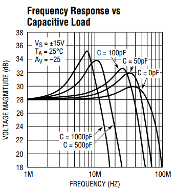
I searched a lot for op-amps with a high cutt off freqeuncy an d I found many , but when I look at the data sheet for Freqeuncy VS Outut Voltage the freqeuncy stops before 10Mhz. The gain VS freqeuncy graph looks fine and shows that it can amplify untill 30 Mhz and more.

enter image description here

Here is a picture of the nearest one I found ,at 26db (20 volts) the freqeuncy I think approches 30 or 40 Mhz , is that correct?

Links : The first the voltage isn't amplified properly at 30 Mhz and stops amplifying before 10 Mhz almost , second link similar problem , but gain seems to be OK.

First link Second link

\$\endgroup\$
13
  • \$\begingroup\$ Have you tried looking for one with a GBW of at least 680MHz? \$\endgroup\$ Commented Jun 12, 2015 at 5:41
  • \$\begingroup\$ Actually I have. I looked for higher bandwiths hoping the cutt of frqeuncy will be higher , but its either the same as the pics I attached or the graph of the voltage amplification isn't in the data sheet, only gain graphs. \$\endgroup\$ Commented Jun 12, 2015 at 5:46
  • \$\begingroup\$ You know that a voltage amplification of 20 is a gain of 26dB, right? \$\endgroup\$ Commented Jun 12, 2015 at 5:48
  • \$\begingroup\$ Yes .I added a pic in the question that shows 20 dB the highest I found , but doesn't show what happens at 26 dB \$\endgroup\$ Commented Jun 12, 2015 at 6:12
  • \$\begingroup\$ Did you try searching on digikey? Probably you can search by GBW product. \$\endgroup\$
    – user57037
    Commented Jun 12, 2015 at 7:41

2 Answers 2

9
\$\begingroup\$

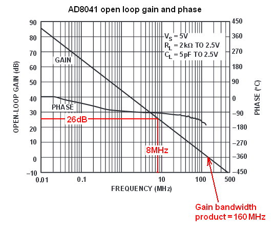
Your first op-amp is the AD8041 and most of the story is revealed in the open-loop gain response: -

enter image description here

If you want 26 dB of gain (20 v/v) you can't have a bandwidth greater than about 8 MHz - that's the limits that this device is capable of. This is what GBW means: -

Gain x Bandwidth is usually constant (or thereabouts) for a normal op-amp - you can see that the bandwidth is 0dB (unity gain) at 160MHz. Take a look at the gain at 16MHz to the left of the red arrow - the gain is 20dB (i.e. a gain of 10) AND 10 x 16MHz = 160MHz.

At 1.6 MHz the gain is 40dB etc etc..

The picture in the question is of some importance for amplifier designers but it's the open loop gain graph that tells you what the GBWP is.

Choose an op-amp that has the gain AND bandwidth. The AD9631 I reckon is slightly worse than the AD8041.

Once you have got that op-amp spec sorted out check that the slew rate capability of the device will give you the desired p-p output level that you need. Data sheets sometimes have graphs or pictures that show the sort of amplitude you can expect so, read the data sheet. It's your best friend when picking the "right" op-amp.

\$\endgroup\$
7
  • \$\begingroup\$ OK @Andy aka great much appretiated. But I still have one doubt about the pic in my question , which is the magnitude of voltage in dB. At 26 dB (20 volts as the amplification desired) , the frequncy doesn't cutt off at 10 Mhz and continues for more than 30 Mhz for the 50 pF capacitor. Does that mean it is doing the job of amplification at this freqeuncy ? \$\endgroup\$ Commented Jun 12, 2015 at 11:47
  • \$\begingroup\$ That is output voltage magnitude and not gain. The gain config will likely be unity for this test and the input level will therefore be 28 dBV. Another interesting point is what I mentioned in my answer. Despite GBP being 160MHz the output in your graph is clearly falling away seriously before 160MHz is reached - this is likely the effect of slew rate limiting. \$\endgroup\$
    – Andy aka
    Commented Jun 12, 2015 at 11:54
  • \$\begingroup\$ I may have made a mistake explaining my point or what I'm looking after. I'm sorry not very good with data sheets, but I want the output voltage to be amplified by 20 ( 20 is what I'm designing for the inverting configuration gain) , while the frequency doesn't cutt off at 30 Mhz. This is what I'm seeing in the pic in the question , the magnitude continues after 30 Mhz. But I don't think I'm right. \$\endgroup\$ Commented Jun 12, 2015 at 12:01
  • \$\begingroup\$ Above the frequency where the magnitude starts to sag there will be a linear fall in amplitude (dB) with log of frequency hence the GBP graph. You won't get a sudden cut-off above 30MHz - it will fall away at 20 dB/ decade in frequency. \$\endgroup\$
    – Andy aka
    Commented Jun 12, 2015 at 12:07
  • 1
    \$\begingroup\$ It's trying to tell you that loads connected to the op-amp (such as cables) will cause problems and you need to be aware of how these capacitove loads affect the frequency response of the op-amp. It's never plain sailing when you lift the rocks up! \$\endgroup\$
    – Andy aka
    Commented Jun 12, 2015 at 12:42
6
\$\begingroup\$

as "Andy aka" already wrote you've tried to break the GBW limit of an operational amplifier and didn't got the gain you've expected. For your application you need an OpAmp with a GBW of roughly 700Mhz.

Well, those exist. They aren't cheap and due to their high frequency they are very picky about PCB layout.

Fortunately a different kind of OpAmps exist that don't tie gain and band-width together. These are called "Current Feedback OpAmps". They have different characteristics than the ordinary "Voltage Feedback OpAmps". They can't do all the things your Voltage Feedback OpAmps can, and they have some hard restrictions about what you can put into the feedback path of the OpAmp, but for amplification jobs they might be an alternative choice for you.

One specimen of that class that I have made very good experience with is the LT1227 OpAmp. It has a transit frequency of 140Mhz regardless of gain (within reason of course). You can even buy it in DIP8 package if you're using through hole parts for prototyping. And they are available and not that expensive.

Ultra Short Prime on Current Feedback OpAmps:

  • The CFA is very picky about what happens in it's feedback path, e.g. the components you put between it's output and it's inverting input. Different parts have different requirements, but generalized you'll end up with a fixed, relative low resistor. For the LT1227 that is 1kOhm.

  • You must never put a capacitor in the feedback-loop, so all integrator circuits and some filter circuits are not possible to realize.

  • The positive and negative input have very different characteristics. While the positive input terminal is high impedance like in a good Current Feedback OpAMp, the negative input is usually low impedance. Also the inputs aren't matched at all.

In your application you want an inverting amplifier. This is not ideal for a CFA, but works. Since the feedback resistor is fixed at 1KOhm, your input resistor will be 50Ohm, so you end up with an input impedance of roughly 1KOhm. That's not much, but may work for you.

If you can change your circuit to the non-inverting configuration the input impedance restriction will not be a problem.

TL;DR: It is worth looking into Current Feedback OpAmps if you want high gain with high bandwidth and don't plan to do anything fancy except amplification.
\$\endgroup\$
2
  • \$\begingroup\$ There is another big advantage of current-feedback amps: They have nearly "fantastic" slew rate capabilities. \$\endgroup\$
    – LvW
    Commented Jun 12, 2015 at 15:50
  • \$\begingroup\$ @LvW Oh yes, that's true. \$\endgroup\$ Commented Jun 12, 2015 at 16:06

Your Answer

By clicking “Post Your Answer”, you agree to our terms of service and acknowledge you have read our privacy policy.

Not the answer you're looking for? Browse other questions tagged or ask your own question.