0
\$\begingroup\$

I made a prototype to test a few logic gates and found out that

  1. My AND gate (7408) Works like an OR Gate.

  2. My OR Gate (7432) is always on

  3. My XOR Gate (7486) is always off

  4. My NOT Gate (7404) works.

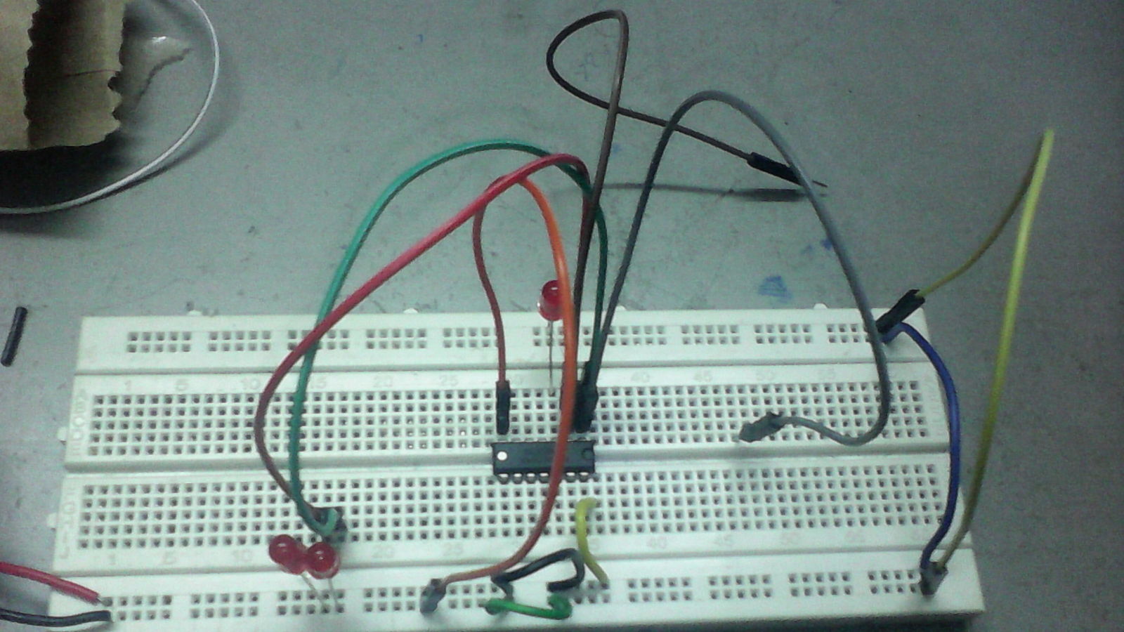
This is my test setup - Setup

The grey and Brown hanging wires are inputs, the LED up top is output. The current chip is the 74HC08N AND by TI.

Sometimes, the gates randomly work too.

EDIT

Adding Resistors and pulling to GND fixed all but the XOR (74F86PC) Gate, which still does not respond (With bypass capacitors, etc)

I Am Running at 3 V

So, help? Thanks! These are my first circuits, so a bit dirty, sorry.

\$\endgroup\$
8
  • 2
    \$\begingroup\$ The bypass capacitor is missing. There must be a 0.1uF ceramic capacitor connected directly between the power and ground pins of each IC, to compensate for the parasitic inductance of the leads. This is especially important with solderless breadboards and long wires. \$\endgroup\$
    – MarkU
    Commented Sep 11, 2015 at 18:57
  • 2
    \$\begingroup\$ Are you using current limiting series resistors for the LEDs? \$\endgroup\$
    – jippie
    Commented Sep 11, 2015 at 18:58
  • 2
    \$\begingroup\$ Related: electronics.stackexchange.com/questions/2272/… \$\endgroup\$
    – MarkU
    Commented Sep 11, 2015 at 18:58
  • 5
    \$\begingroup\$ I don't see any current limiting resistors in series with your LEDs? I think you need them. \$\endgroup\$
    – Ricardo
    Commented Sep 11, 2015 at 18:59
  • 1
    \$\begingroup\$ Are you returning the LEDs to +5V? A positive logic AND is a negative logic OR... Learn to draw schematics (e.g. in the schematic editor) ... it's at least as important as your wiring experiments. \$\endgroup\$
    – user16324
    Commented Sep 11, 2015 at 21:27

1 Answer 1

3
\$\begingroup\$

For CMOS logic parts like the 74HC family, the inputs are very high impedance, and don't assume any particular level when left unconnected. They must always be connected either directly, or through a resistor, to Ground or Vcc, in order for the chip to reliably see them as Low or High. ALL unused inputs MUST be connected to Vcc or Ground, even on the unused gates in the chip.

For bipolar TTL (plain 74xx, 74LS, 74ALS) the inputs source current, so will normally appear as high when not connected, and must be connected to Ground to be seen as a low.

As the comments mention, a bypass capacitor is desireable, but the lack of one wouldn't cause a problem with the simple test circuit you are using.

\$\endgroup\$
3
  • \$\begingroup\$ Thank you for your answer. I tried pulling all unused inputs to ground, but it still behaves the same. Maybe the capacitor is the culprit. I haven't checked that yet. \$\endgroup\$ Commented Sep 12, 2015 at 2:25
  • \$\begingroup\$ You NEED 300 ohm (or so) resistors in series with your LEDs to control the current through the LEDs, and to permit the chip inputs to rise above the 1.8 volt forward voltage of the LEDs. What is your power supply voltage? \$\endgroup\$ Commented Sep 12, 2015 at 3:51
  • \$\begingroup\$ The XOR Still doesn't work, though \$\endgroup\$ Commented Sep 12, 2015 at 14:26

Your Answer

By clicking “Post Your Answer”, you agree to our terms of service and acknowledge you have read our privacy policy.

Not the answer you're looking for? Browse other questions tagged or ask your own question.