2
\$\begingroup\$

I need a active safety circuit to clamp voltages to the range of 0-200mV, independent of temperature and very precisely. I have simulated, using TINA-TI, 4 precision clamps in series to do this, see design below: the first two precision clamps ensures the lower clamp voltage and the last two ensures the top clamp voltage. There is an offset for some reason if the buffer is not included. clamp circuit updated

However, this is a very component heavy design, and I'm wondering if there is a simpler method? Thanks for reading.

Edit: Ideally I'd like the full swing (0-200mV) with precision to 0.001V. The input will come from a DAQ with -10~10V swing. Also, the load is around 50 ohms.

\$\endgroup\$
10
  • \$\begingroup\$ 200mV in the title, 0.2mV in the detail - which is it? \$\endgroup\$
    – Andy aka
    Commented Nov 9, 2015 at 13:44
  • \$\begingroup\$ oops! my bad Andy. It is 200mV. \$\endgroup\$
    – Sam
    Commented Nov 9, 2015 at 13:45
  • \$\begingroup\$ Yeah I though you meant that hence my amendment in my answer. \$\endgroup\$
    – Andy aka
    Commented Nov 9, 2015 at 13:46
  • \$\begingroup\$ So what's the maximum voltage that you hope to clamp? I'm not asking for the maximum of the range you want to clamp to. Is the max conceivable input voltage +/-1V as in your graph? \$\endgroup\$ Commented Nov 9, 2015 at 13:56
  • \$\begingroup\$ @RespawnedFluff thanks for the reminder. The input will come from a DAQ with either 0~5v or -10~10V capability (Labjack U3 +analog extension: labjack.com/accessories/ljtick-dac). \$\endgroup\$
    – Sam
    Commented Nov 9, 2015 at 14:59

1 Answer 1

2
\$\begingroup\$

low voltage clamp circuit (0-200mV)

I'd amplify the input signal so that the new desired clamping levels were 0V and 5V. Then I'd use a rail to rail amplifier running on a 0V and 5V supply. Then I'd attenuate the output by 25 so that 5v became 0.2V and 0V remained at 0V.

If the frequency isn't too high, a simple R2R op-amp should work nicely but the devil's in the detail so maybe a simulation is called for?

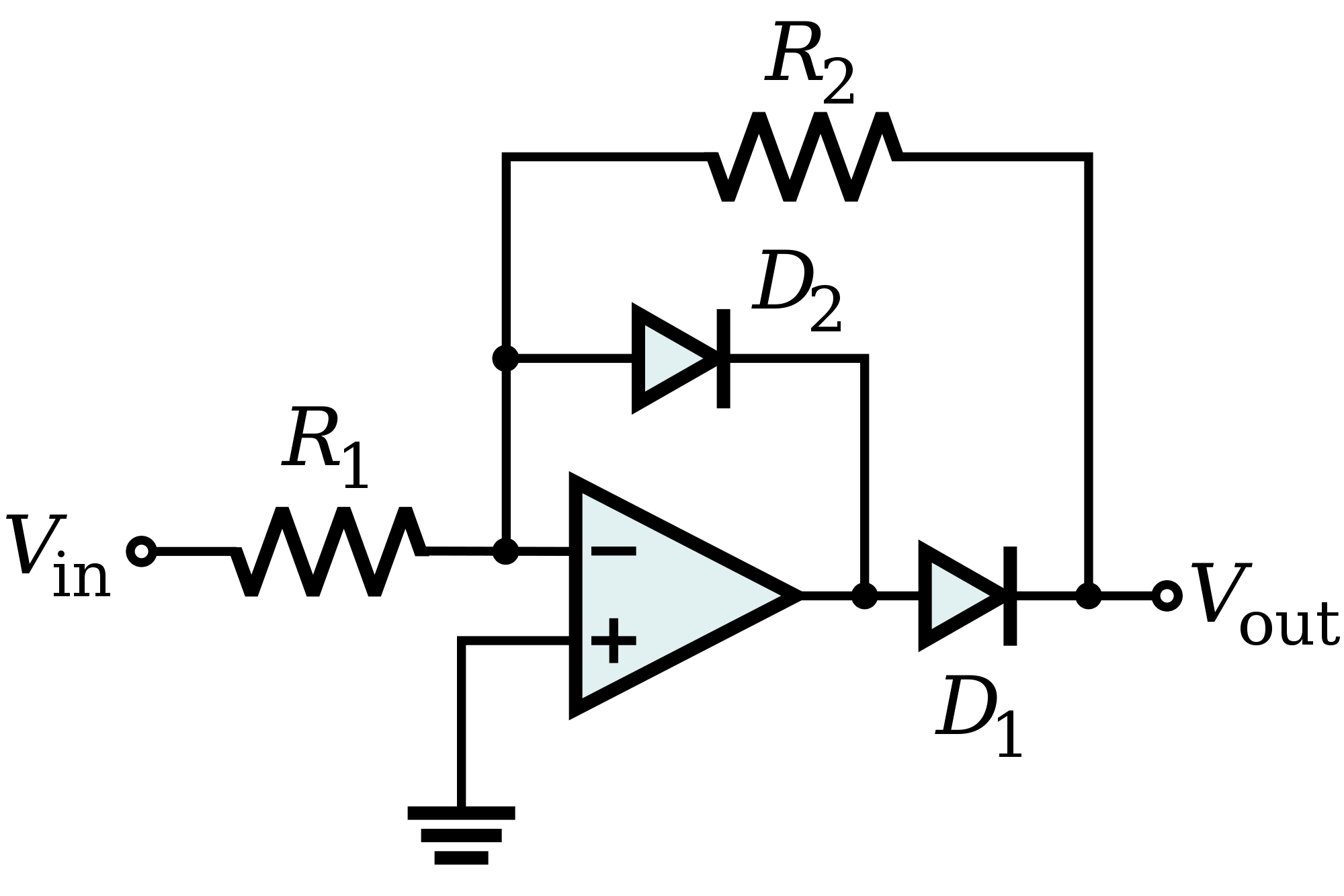
Following question amendment I propose this, a precision rectifier: -

enter image description here

It needs to run from split supply rails but will only produce a positive output i.e. it will "clamp" at 0V. Because the circuit is "inverting", a further inverting amplifier will need to be used before this circuit.

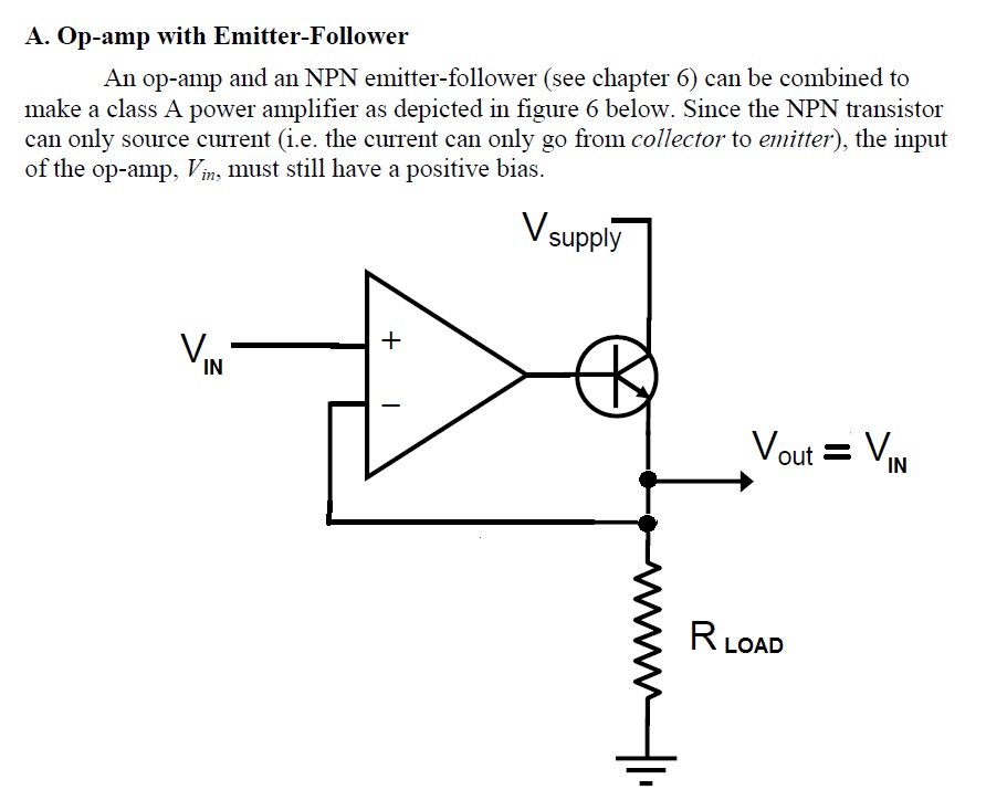
I would also consider using a BJT to aid as a voltage follower in order to drive the load. Maybe like this: -

enter image description here

Rload could be as low as a few ohms but the important thing is that the op-amp has the BJT (or MOSFET) inside the closed loop thus maintaining regulation on the output. The output should be capable of supplying a fair bit of current but as you only need 0.2/50 mA it shouldn't be an issue.

\$\endgroup\$
8
  • \$\begingroup\$ Hi Andy, I took a look at available op amps and the minimum for the negative rail seems to be around 0.8V. This translates to losing control from 0-0.032V at the output. Ideally I'd like the full swing (0-200mV) with precision to 0.001V, but this solution is overall better due to it using only one op-amp and thus have a lower chance of failure. I should also mention that the load is a low impedance of around 50ohms. I'll be simulating soon. Thanks. \$\endgroup\$
    – Sam
    Commented Nov 9, 2015 at 17:01
  • \$\begingroup\$ You need a rail to rail op-amp not any old standard op-amp. OPA333 springs to mind as does the AD8605/06/08 - there are plenty that will work but will only probably limit at 50mV of either rail so that's a 2mV accuracy after voltage reduction. Regards the 50 ohm load that's a late new entry!! \$\endgroup\$
    – Andy aka
    Commented Nov 9, 2015 at 18:10
  • \$\begingroup\$ With such a large negative input there will likely be other problems so I suggest using an amplifier with +/- supplies but one that is incapable of producing a negative output voltage. I'll draw something. \$\endgroup\$
    – Andy aka
    Commented Nov 9, 2015 at 18:13
  • \$\begingroup\$ Yes, sorry for adding the load resistance late. I'm thinking of adding a voltage buffer in any case, and a 2V zener. However, safety is quite a concern and I'm trying to figure out the most fail-safe design. \$\endgroup\$
    – Sam
    Commented Nov 9, 2015 at 18:16
  • \$\begingroup\$ thanks for the update. The only thing I'm worried about is the reliability and accuracy of hard limiting via the positive supply rail. \$\endgroup\$
    – Sam
    Commented Nov 9, 2015 at 19:15

Your Answer

By clicking “Post Your Answer”, you agree to our terms of service and acknowledge you have read our privacy policy.

Not the answer you're looking for? Browse other questions tagged or ask your own question.