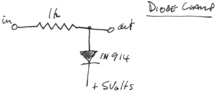
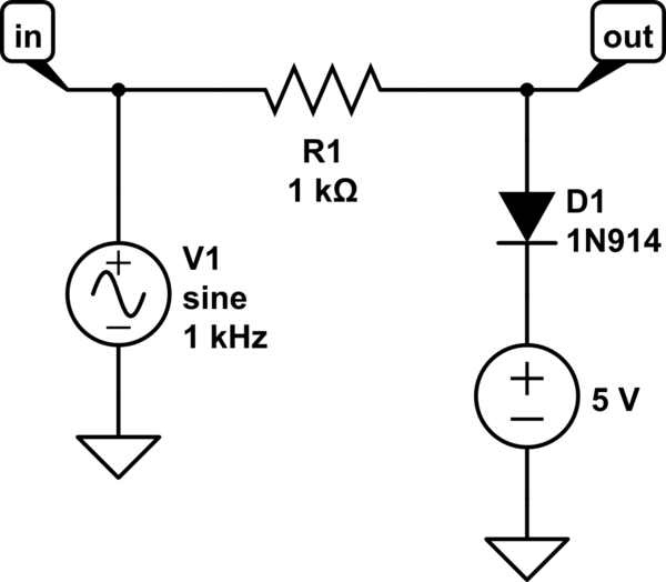
Working through Learning the Art of Electronics, Hayes T, I'm stuck trying to build the diode clamp in Figure 3L.7 on page 137, as below:
The text says to, "Drive it with a sinewave from your function generator... ...and observe the output." So presumably +ve from the function generator connects to "in", +ve from the power supply to "+5 volts", and scope probe to "out".
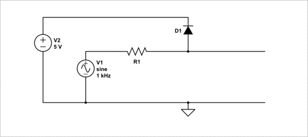
Having searched the web and studied various clamp schematics, I still can't work out the answer to my question which is, where to put the ground leads from function generator, power supply and oscilloscope?
Thanks
David


