0
\$\begingroup\$

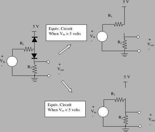
I understand the use of diodes as switches or "clamp circuits", however I needed a little clarification in this diagram, taken from the site https://www3.nd.edu/~lemmon/courses/ee224/web-manual/web-manual/lab5/node9.html

enter image description here

I understand that when Vin>5 V, the top diode to the power supply is forward biased, and ~shorted, and when Vin< 5 V the top diode is reverse and open. However is the bottom diode to R2 and ground not forward biased in both cases? I don't quite see how that arm is always an open circuit if we don't know Vout. Thanks!

\$\endgroup\$
3
  • 3
    \$\begingroup\$ Yes, the source material is wrong and the lower diode should be forward biased in both cases (assuming Vin > 0). \$\endgroup\$
    – The Photon
    Commented Mar 12, 2018 at 22:49
  • 1
    \$\begingroup\$ This resource made some errors/ \$\endgroup\$
    – D.A.S.
    Commented Mar 12, 2018 at 23:18
  • 2
    \$\begingroup\$ Thanks! As the saying goes, "The problem with the internet is that you cannot always trust its veracity". -Abraham Lincoln \$\endgroup\$
    – daFireman
    Commented Mar 13, 2018 at 2:10

2 Answers 2

1
\$\begingroup\$

I don't think that the annotations are really correct, and the schematic is not what was intended.

Anyway...

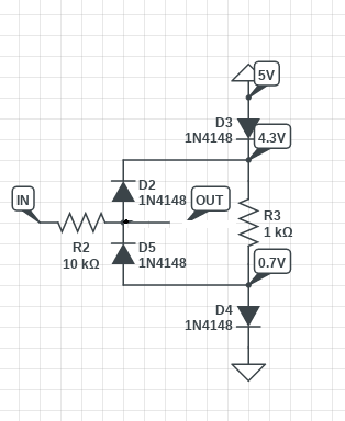
Obviously the top diode will clamp over voltages, but it will clamp them to 5.7V. By having the lower diode, 0.7V is dropped, and so when clamped, Vout does not exceed 5V. However there is a series diode drop in the output - probably not very good.

But why?

The clue may be in the word "comparator". Bad things such as state inversion can happen when inputs to comparators and opamps go outside the max operating range. The designer may have a hard need to keep the input from exceeding VDD.

This is how you would clamp without exceeding the rails, and without having a diode drop in series:

enter image description here

Note that diode clamps like this are soft clamping - current will start to flow when VIN reaches 4.8-4.9V, so ADC reading for example will be wrong at the edge (4.9V) as the clamp starts to conduct.

\$\endgroup\$
0
\$\begingroup\$

It is something of a play on words. With 5 volts in, assuming both diodes are the same type, the Vout of both diodes is the same. The fact that one diode had a resistive load changes nothing.

If the load is heavy enough it will affect the sources ability to provide 5 volts, therefore any voltage drop would be the same for both diodes.

It was not mentioned in the question, so it was assumed these were 'ideal' diodes with no forward voltage drop, but in real-world conditions they would have a .5 to .7 volt drop. To 'get' 5 volts out you need 5.7 volts as Vin.

\$\endgroup\$
2
  • \$\begingroup\$ @ThePhoton. Would someone please comment on the down vote, seeing that there were no up votes on these answers. \$\endgroup\$
    – user105652
    Commented Mar 13, 2018 at 2:52
  • \$\begingroup\$ I guess I will ignore ambiguous questions from now on... \$\endgroup\$
    – user105652
    Commented Mar 13, 2018 at 3:07

Your Answer

By clicking “Post Your Answer”, you agree to our terms of service and acknowledge you have read our privacy policy.

Not the answer you're looking for? Browse other questions tagged or ask your own question.