0
\$\begingroup\$

I'm building a simple ring counter with two jk flip-flop. I'm using 74HC76 integrated that contains two jk.

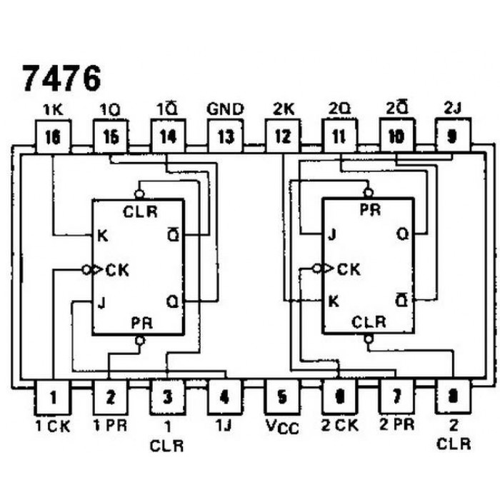
This is the integrated pinout:

enter image description here

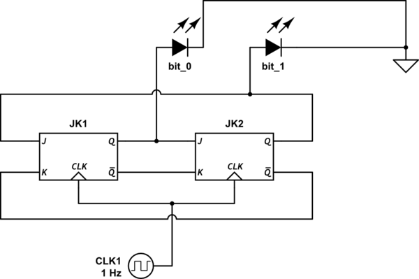
This is my schematic (very basic):

schematic

simulate this circuit – Schematic created using CircuitLab

To build a working circuit it's necessary that you connect pin 5 to Vcc (5V) and pin 13 to GND. But...

The problem is that in the circuit that I'm observing on my desk the ring counter only works when pin 5 (Vcc) is unwired. It means that if I wire pin 5 to Vcc I got always 10 output. Is that possible? If no what's the matter of my circuit?

I've tried all:

  • I've substituted the integrated -> same problem
  • I've checked another time pin connection -> same problem
  • I've changed wires -> same problem

EDIT: I initialize the first jk with 1 using a button and preset and clear pin.

\$\endgroup\$
6
  • 1
    \$\begingroup\$ First: Do not, ever, disconnect the VCC pin when debugging, because that breaks chips. Second: what are you doing with the Preset and Clear pins? (i.e. J and K propagate 1 to 1, if you don't preset and clear one on initialisation, you will not know what happens, but them both starting with 1/0 or both with 0/1 is quite likely) \$\endgroup\$
    – Asmyldof
    Commented Dec 9, 2015 at 22:54
  • \$\begingroup\$ JK1 and JK2 need to initialize in opposite states, don't they? How do you ensure this? Also, you should use resistors in series with the LEDs \$\endgroup\$
    – user28910
    Commented Dec 9, 2015 at 23:04
  • \$\begingroup\$ @Asmyldof: Thanks for your advice. About Preset and Clear pin I'm managing them well: I've a button that sets the starting 1 in the first jk, so I think that the problem isn't about Preset or Clear pin. \$\endgroup\$
    – xdola
    Commented Dec 9, 2015 at 23:04
  • \$\begingroup\$ @user28910 : I've just edited my question \$\endgroup\$
    – xdola
    Commented Dec 9, 2015 at 23:07
  • \$\begingroup\$ On CMOS parts, all unused inputs must be connected, directly or through a resistor, to either Vcc or ground, whichever is required to make the part work as required. For the Preset pin where you have a switch to pull it to ground, you must also have a resistor (5K - 10K) to Vcc to ensure the preset pin is high when the switch is not taking it low. \$\endgroup\$ Commented Dec 9, 2015 at 23:27

2 Answers 2

3
\$\begingroup\$

Without a resistor in series with each LED is is likely that the corresponding Q output is being dragged down to a voltage that is not high enough to be recognized as a legitimate high level by the following J input.

\$\endgroup\$
2
\$\begingroup\$

On CMOS parts, all unused inputs must be connected, directly or through a resistor, to either Vcc or ground, whichever is required to make the part work as required. For the Preset pin where you have a switch to pull it to ground, you must also have a resistor (5K - 10K) to Vcc to ensure the preset pin is high when the switch is not taking it low.

\$\endgroup\$

Your Answer

By clicking “Post Your Answer”, you agree to our terms of service and acknowledge you have read our privacy policy.

Not the answer you're looking for? Browse other questions tagged or ask your own question.