1
\$\begingroup\$

I would like to sample the acceleration of the wheel axis (vertically and left-right) N times per rotation (for example once per spoke, but not necessarily). The data would be processed with Arduino.

I have no ABS system in my car.

I can mount the accelerometer easily, but I don't know how to synchronise the sampling with the rotation of the wheel.

Which sensor could be easily mounted on lightweight wheels (no steel wheels) and work reliably in such dirty and vibrating environment?

My current option is only a Hall sensor on the brake caliper, together with a strong magnet fixed in each spoke of the alu wheel, to get about 6 readings per wheel rotation.

Still, I'm not sure the Hall sensor would be close enough to the magnet, and I'm not sure a rare-earth magnet would survive the vibrations of the wheel.

Any other options? I'm thinking also to place the N magnets in the wheel axis itself, as long as it is feasible. Still, is the Hall the best choice?

Edit

Of course, if you think that the magnets in the rims is a good solution and that it can withstand the stress, you can support that option. Additional solutions are fine, but not necessarily required.

\$\endgroup\$
4
  • \$\begingroup\$ how do you think the hall sensor can help in measuring the wheel acceleration? you need a radio link, or I completely misunderstood the question \$\endgroup\$ Commented Apr 20, 2016 at 14:46
  • \$\begingroup\$ The Hall only synchronises the timing, the accelerometer measures the acceleration. \$\endgroup\$
    – FarO
    Commented Apr 20, 2016 at 14:56
  • \$\begingroup\$ Attaching magnets to the disk is going to cause balance problems unless you're careful. \$\endgroup\$ Commented Apr 20, 2016 at 15:34
  • \$\begingroup\$ To the disk? I mentioned only the spokes of the wheel and I mentioned one magnet per spoke exactly to avoid issues with balancing. \$\endgroup\$
    – FarO
    Commented Apr 20, 2016 at 15:35

1 Answer 1

3
\$\begingroup\$

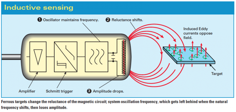
An active inductive proximity sensor can detect the passing of the aluminium spokes: -

enter image description here

It produces a high frequency magnetic field and detects the eddy currents induced in conductive objects in its path. One thing to watch out for is operating frequency - if you require high resolution to precisely detect the spoke and judge the "correct" position then operating at higher frequencies is necessary. In effect the oscillator frequency can be regarded as sampling the eddy current disturbance so you'll want plenty of cycles of AC for each spoke that passes.

I use them on aero engine tests looking at blade wobbles on the turbines.

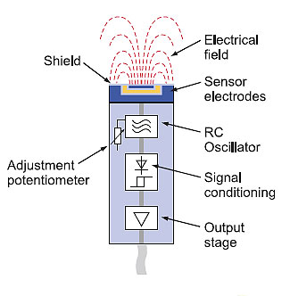
A similar solution might be a capacitance probe - the tip of the probe is excited with an AC source and the amplitude changes as a spoke passes by: -

enter image description here

\$\endgroup\$

Your Answer

By clicking “Post Your Answer”, you agree to our terms of service and acknowledge you have read our privacy policy.

Not the answer you're looking for? Browse other questions tagged or ask your own question.