0
\$\begingroup\$

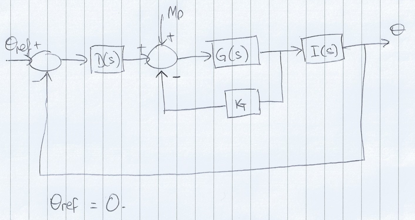
I have a block diagram that I am trying to get the transfer function for but can't seem to figure it out, I am sure that I am making it more difficult than it needs to be but still can't get it. The diagram is below and any help would be great!

enter image description here


Edit
So far I have got myself to this point but I am unsure if it is correct: $$\frac{\theta }{M_p}=\frac{G(s)(I(s)-K_t)}{1+D(s)G(s)(I(s)+K_t)}$$ I feel I should try solving the inner loop and then the outer but I can't work out how to put the inner loop in one function. Any ideas?

EDIT INNER LOOP SIMPLIFICATION
enter image description here

\$\endgroup\$
5
  • \$\begingroup\$ I see two loops - one inner and one outer loop. Do you know how to write the transfer function for a single feedback loop? \$\endgroup\$
    – LvW
    Commented Apr 30, 2016 at 15:54
  • \$\begingroup\$ I usually set the inner loop as some function (A simple variable that lives within the overall expression) and then get the transfer function of the overall; Let \$Loop_{inner}\$ be \$F_{li}\$; now get the transfer function of the overall loop and plug in the inner loop afterwards. \$\endgroup\$ Commented Apr 30, 2016 at 16:58
  • \$\begingroup\$ @PeterSmith That's the thing, I can't work out what the Inner loop is when there are two inputs... I've got the outer no problemo as I've already had to get that - just can't decipher the inner. Outer Loop = \$\frac{\theta}{M_P}=\frac{U(s)I(s)}{1+D(s)U(s)I(s)}\$ where \$U(s)\$ is the inner loop \$\endgroup\$
    – MrPhooky
    Commented Apr 30, 2016 at 17:00
  • 1
    \$\begingroup\$ I would separate the inputs at the summing node; in the inner loop use the feedback from \$K_t\$ and \$M_p\$ and then use this as a summing node from the output of \$D_s\$. A summing node with 3 inputs cann be viewed as two summing nodes. \$\endgroup\$ Commented Apr 30, 2016 at 17:04
  • \$\begingroup\$ @PeterSmith Hi, I think I get what you've said, I've tried to do, please see the edit in the question - is this what you meant? \$\endgroup\$
    – MrPhooky
    Commented Apr 30, 2016 at 17:13

1 Answer 1

1
\$\begingroup\$

I find it useful to work backwards from the system output signal to a convenient summing junction output, and then equate this output to the summing junction's inputs.

Thus, the output from the 2nd SJ is \$\large\frac{\theta}{I(s)G(s)}\$

The inputs to that SJ sum to: \$ M_P-\theta \:D(s)-\large\frac{\theta}{I(s)}K_T\$

Equating these two expressions gives: $$\frac{\theta}{M_P}=\frac{I(s)G(s)}{1+K_T G(s)+D(s)I(s)G(s)}$$

\$\endgroup\$
3
  • \$\begingroup\$ That is what I was getting in the end! Great, thanks - however, if it would be possible, how would I get this in a form to use in a root locus? \$\endgroup\$
    – MrPhooky
    Commented Apr 30, 2016 at 20:04
  • \$\begingroup\$ I have worked it out now thanks, spent hours being a fool! \$\endgroup\$
    – MrPhooky
    Commented Apr 30, 2016 at 20:57
  • \$\begingroup\$ For root locus, the characteristic equation is: \$1+K\frac{GID}{1+K_TG}=0\$ , where \$0\le K\le \infty\$, is the forward gain \$\endgroup\$
    – Chu
    Commented Apr 30, 2016 at 21:02

Your Answer

By clicking “Post Your Answer”, you agree to our terms of service and acknowledge you have read our privacy policy.

Not the answer you're looking for? Browse other questions tagged or ask your own question.