3
\$\begingroup\$

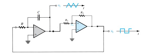
i was Implementation of square and triangular wave generator using op-amps LF353.

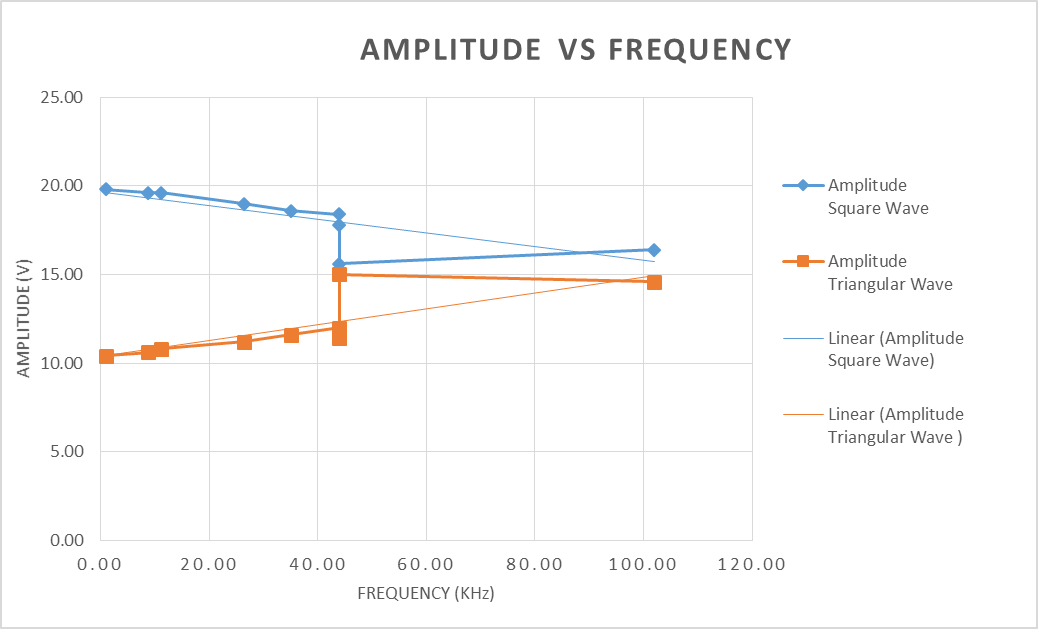
I observed that when I choose different values of Resistor and Capacitor for different frequencies, with increasing frequency the amplitude of Square wave decreases and amplitude of triangular wave increases. If I extrapolate a trend line in the graph of Amplitude Vs frequency they join a common point where both amplitudes become the same.

Why the saturation voltage(square wave amplitude) is decreasing and triangular amplitude increasing? output Note: There are two points at 45Khz. The lowest amplitude point of square wave are taken when I selected a greater value of capacitor and smaller value of resistor to form the same combination for 45KHz.

Circuit Diagram: R1 and R2 are capt constant: R1=1kΩ & R1=2KΩ circuit

\$\endgroup\$

4 Answers 4

2
\$\begingroup\$

I obseved that When i choose different values of Resistor and Capacitor for different frequencies, with increasing frequency the amplitude of Square wave decreases

It will because a lower value of "R" loads the output of the op-amp more and its saturation voltage increases. Remember the integrator input resistor feeds a virtual ground so it acts just like a load resistor to ground on the output of the comparator.

and amplitude of triangular wave increases

As you raise the operating frequency, the time it takes for the comparator to switch becomes more dominant in the period of the signal frequency being generated. This "extra time" allows the triangle wave (formed by the integrator) to rise to slightly higher peak values.

When using an op-amp as a comparator, the output transistors enter saturation and it can take several micro-seconds to recover from saturation.

I don't think the the two other answers understand what is happening in this circuit - the whole point is that the triangle p-p amplitude is dictated by the hysteresis of the comparator; theorestically, with perfect op-amps, the triangle wave p-p amplitude is constant.

\$\endgroup\$
5
  • \$\begingroup\$ I could not get the point " lower value of "R" loads the output of the op-amp more and its saturation voltage increases. Remember the integrator input resistor feeds a virtual ground so it acts just like a load resistor to ground on the output of the comparator." \$\endgroup\$ Commented Nov 20, 2016 at 20:38
  • 1
    \$\begingroup\$ @MasoodSalik do you understand that the integrator's input resistor acts as a load to the output of the comparator? This is because at the inverting terminal of the integrating op-amp, the voltage is a virtual ground i.e. 0V as per the non-inverting terminal. If you don't understand this you need to do some work understanding basic op-amp circuits. \$\endgroup\$
    – Andy aka
    Commented Nov 20, 2016 at 21:46
  • \$\begingroup\$ Got it. Thats why when i used very low value of R for some particular combination of frequency. A Peculiar voltage spikes in triangular waveform generator circuit were observed. But for some other combination of R and C (in which R was large) no spikes were there. As shown in picture pictub.club/image/jdR5o \$\endgroup\$ Commented Nov 20, 2016 at 22:02
  • \$\begingroup\$ There is a question about these peculiar spikes electronics.stackexchange.com/questions/237570/… \$\endgroup\$ Commented Nov 20, 2016 at 22:08
  • 1
    \$\begingroup\$ @MasoodSalik the spike on top of the triangle is due to the integrator being unable to change direction instantaneously when the square wave goes from negative to positive and what happens is that the "edge" forces its way through R and C to the op-amp output. In other words, you would need a faster op-amp capable of driving higher current or a bigger value resistor. \$\endgroup\$
    – Andy aka
    Commented Nov 21, 2016 at 8:23
2
\$\begingroup\$

Your left operation amplifier with its RC components are an active low-pass filter - that's their purpose, if you think about it!

So what it mathematically is is a "integrator". And that's the whole reason the amplitude of the triangles decrease with shorter period time (=higher frequency). When you integrate a constant (high input) for a long time, your integral will have a higher value than when you integrate the same constant for a short time.

Atop of that, real-world amplifiers also have finite bandwidths, and the gain of the semiconductor circuitry inside an opamp goes down with frequency, and at some point the idea that an opamp has "very very high gain" just breaks down. However, at your cute 45 kHz, that's probably not the situation here, unless you're using something extrodinarily slow (and then, you'd probably know – that opamp would've been labeled as "only for audio applications" or "vintage" or so).

\$\endgroup\$
1
\$\begingroup\$

The triangle waveform and the square wave amplitude ideally (as in using an ideal op-amp/comparator) will not vary with frequency- it would be constant for a given supply voltage.

That is because the amplitude of both is determined by the output saturation voltage of the right-hand op-amp (used as a comparator), which (ideally) depends on the supply voltage only (once it gets there).

To put it succinctly, the left hand op-amp is responsible for the frequency,and the right-hand op-amp for the amplitude.

The problem with an aggregate measurement of a complex waveform is that you may be missing something. In this case, I believe you are missing the fact that the square wave is not really square (and as a result, the triangle wave is not really triangular).

The op-amp (used as a comparator with hysteresis proportional to the supply voltage as determined by the R1/R2 ratio) has a finite slew rate and thus the edges of the square wave are really ramps. Thus the square wave spends less time at the limits. Similarly the triangle wave is created by integrating the square wave, so the slopes of the triangle wave will not be straight lines, but will curve upward or downward on rising/falling slopes.

A secondary effect is that some op-amps take a long time to recover from saturation so the output of the comparator op-amp will be delayed by a (more-or-less) fixed amount on each edge. However that would tend to make the output triangle waveform amplitude increase with frequency and would not affect the square wave, so I don't think that's a factor here.

Edit: Andy is also correct that loading of the op-amp/comparator output may be a factor. The limiting output voltage of the op-amp will change with loading.

You can avoid this problem by using a proper comparator instead of the right-hand op-amp with hard output limiting using a pair of zeners, say, so the square wave amplitude is controlled. It will transition in nanoseconds (maybe a couple hundred for a really slow comparator) and your variation with frequency will (mostly) go away until you run into the slew rate limit of the left-hand op-amp on the triangle wave slopes.

TL;DR

It's the comparator op-amp slew rate limitation and/or loading making crummy square waves of non-fixed shape and amplitude.
\$\endgroup\$
0
\$\begingroup\$

There are several things going on here.

First, the amplitude of the triangle wave is inversely proportional to the frequency of the square wave it is derived from. This is because the triangle wave generator is a integrator. The integral of a fixed level is a fixed slope. The longer that level is held, the longer the slope continues, and therefore the greater its end-to-end amplitude.

The second affect is less predictable due to how the second opamp threshold-detects the triangle wave. If all components were ideal, the second opamp would flip immediately at each zero crossing of the triangle wave. That would stop that half-triangle and reverse it. That would immediately cause the opposite zero-crossing, which would flip the triangle slope again, which causes another zero-crossing, etc. The result would be infinite frequency with ideal components.

The frequency you actually get is therefore dependent on the non-ideal nature of the components, which is not going to be specified. The propagation delay, rise time, parasitic capacitance, and particularly the slew rate of the second opamap all matter. Basically, this is a bad circuit if you're looking for a predictable frequency.

They way to fix this is to add some hysteresis to the second opamp. Then even with ideal parts, the square wave will flip at known thresholds of the triangle way. The frequency is then deterministic as long as you're not pushing the limits of what the parts can do.

\$\endgroup\$

Your Answer

By clicking “Post Your Answer”, you agree to our terms of service and acknowledge you have read our privacy policy.

Not the answer you're looking for? Browse other questions tagged or ask your own question.