1
\$\begingroup\$

I want to amplify a microphone signal and use the output to drive a speaker and an LEDs bar, all works nicely except for the LEDs bar:
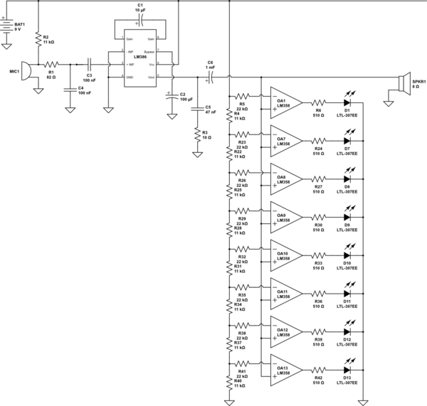
schematic

simulate this circuit – Schematic created using CircuitLab

The LEDs bar is supposed to change level (number of illuminated LEDs) in accordance with the sound level, but all it does is either light all LEDs at once or none. How do I make it proper reactive to sound like this one on YouTube?

\$\endgroup\$
3
  • 2
    \$\begingroup\$ You're doing a linear detection of the output amplitude, this is not going to work. Study how "proper" VU LED meters do this, they use peak-detection of the audio signal and some kind of logarithmic scale. The behaviour that you see is to be expected from this circuit, it does work as it should. It's just an unsuitable design. \$\endgroup\$ Commented Apr 1, 2017 at 19:41
  • \$\begingroup\$ The youtube circuit is probably using an LM3914. That's what I'd say from the layout and the fact there's only one IC involved. \$\endgroup\$
    – JRE
    Commented Apr 1, 2017 at 19:41
  • \$\begingroup\$ You have it connected to the amplified output, and are likely providing to strong a signal for the circuit to know a difference. Change the values of the op amp inputs maybe? \$\endgroup\$
    – Passerby
    Commented Apr 1, 2017 at 19:46

1 Answer 1

3
\$\begingroup\$

You have 8 evenly spaced (in voltage) comparators, you really want a log scale, try making each resistor in the series chain half the value of the one above, this will give you 6dB per LED which is likely to be more satisfactory.

Add a diode, a cap and two resistors to give the thing some dynamics.

Or use a LM3914 or such, lower parts count and that part is made for this job.

\$\endgroup\$
2
  • \$\begingroup\$ Could you please explain more about the extra diode, cap and two resistors? I guess that the diode is to remove the negative part from the output signal but what about the rest?! Also Isn't R/2R ladder network logarithmic or is it linear? \$\endgroup\$
    – razzak
    Commented Apr 1, 2017 at 20:44
  • \$\begingroup\$ What you have drawn is NOT an R/2R ladder because the impedance at the inverting input of the opamps is effectively infinite so the 22k resistors have no effect and could be omitted. Diode connects from the speaker line to one end of a series R/C network where the resistor and cap sets the attack time constant , second (generally higher) resistor across the cap sets the decay time. Voltage on the top end of the cap feeds the opamp network. \$\endgroup\$
    – Dan Mills
    Commented Apr 1, 2017 at 20:52

Your Answer

By clicking “Post Your Answer”, you agree to our terms of service and acknowledge you have read our privacy policy.

Not the answer you're looking for? Browse other questions tagged or ask your own question.