1
\$\begingroup\$

I'd like to implement the following device: it accepts PWM input 5V p-p, and then produce logical zero (GND) at the output when any signal (duty cycle >0) is present and logical one (VCC) otherwise. My first idea was to use RC integrator with an rail-to-rail op-amp and it works, but has a flaw - when PWM signal disappears from the input, it took some time to discharge the capacitor (i.e. output goes slowly from zero to one), although I would like transitions to become as fast as possible. Schematic goes below.
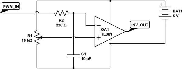
schematic

simulate this circuit – Schematic created using CircuitLab

R1 used to adjust threshold. I also tried to feed op-amp output to noninverting input of another op-amp in same comparator configuration, but it produce constant output regardless of whether PWM input is present. Schematic looks like this:
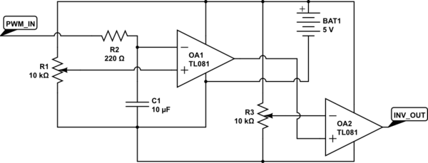
schematic

simulate this circuit

I think I either doing something wrong regarding second op-amp, or missing some concept of using it. Any help will be highly appreciated.

\$\endgroup\$
7
  • \$\begingroup\$ A simple edge detector would tell you if there are transitions on the line. If there are transitions then you might assume there is a PWM signal, if not then you certainly don't. \$\endgroup\$ Commented Apr 4, 2017 at 21:11
  • \$\begingroup\$ @JackCreasey I want output to stay low as long as there is any PWM transitions on the input during some time frame, let's say equal to 1/PWM frequency. Is that what I should get using edge detector? \$\endgroup\$ Commented Apr 4, 2017 at 21:13
  • 5
    \$\begingroup\$ Have you considered using a retriggerable one-shot with its period set slightly longer than the period of your PWM? Something like a 74xx123 might work. \$\endgroup\$
    – brhans
    Commented Apr 4, 2017 at 21:14
  • 1
    \$\begingroup\$ A monostable multivibrator would do well here. Set the RC timing to the PWM frequency. @brhans darn you beat me. \$\endgroup\$
    – klamb
    Commented Apr 4, 2017 at 21:36
  • \$\begingroup\$ Have a look at the NE555 application for a missing pulse detector: ti.com/lit/ds/symlink/ne555.pdf (9.2, Figure 16) ....I assume your signal is not TTL levels since it's 5 vp-p, so the 555 might be suitable for you. \$\endgroup\$ Commented Apr 4, 2017 at 21:37

2 Answers 2

2
\$\begingroup\$

when any signal (duty cycle >0) is present

you need to detect

1) input signal at logic high, or 2) input signal has gone through a low->high transition.

it can be done with logic gates, flip flops, diodes, capacitors and / or a mcu.

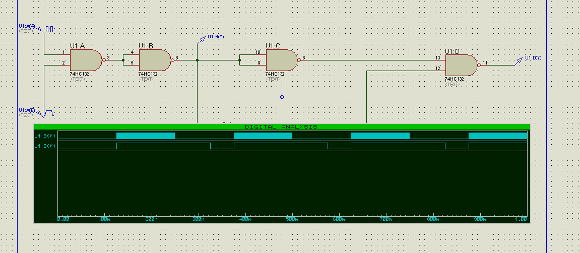
edit: here is one example of how it can be done, with a look-back window.

enter image description here

U1A and U1B form our on-again-and-off-again pwm, for simulation purposes. the output from U1B is being OR's on U1D (actually the two signals, as discussed, are negated and then AND by U1D), to produce the output: it goes high once an active high is detected, or no transition is being detected within the look-back window.

here the look back window is set to be about 100ms but you can change it to your liking.

all done with NAND gates, and some passives.

\$\endgroup\$
0
2
\$\begingroup\$

You need a retriggerable one shot followed by an inverter.

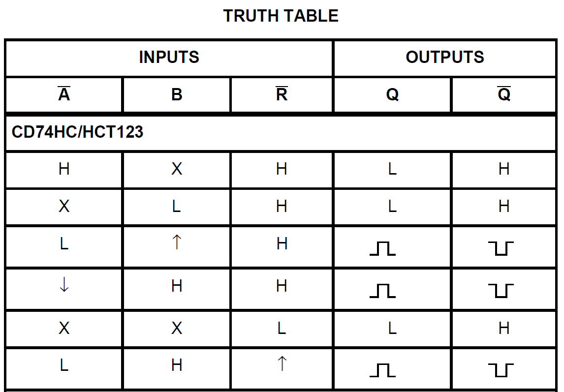
The 74HCT123 (truth table is shown below) is one such integrated circuit – a retriggerable monostable multivibrator. It's available for many logic families (e.g., 74LS123). The output pulse width is set with an external capacitor and resistor. The caps can be large, but for some logic families, large electrolytic caps might require a diode.

enter image description here

Note that there are many modes in which you can use this integrated circuit, and three of them produce timed pulses in response to rising or falling edges (i.e., the rows with up or down arrows).

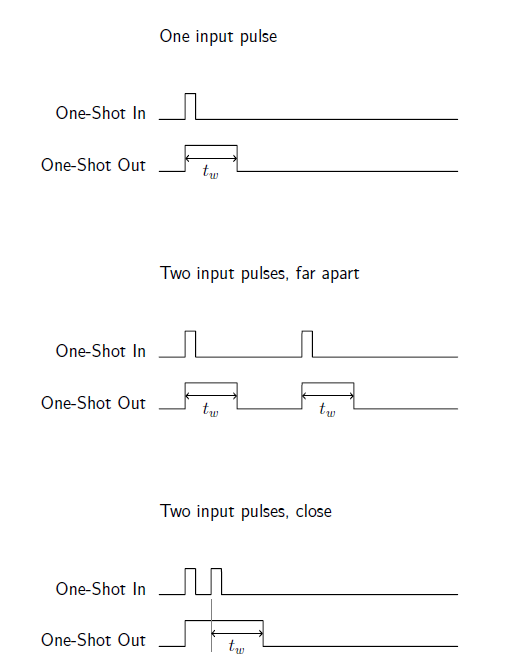
“Retriggerable” means that the output of the integrated circuit will remain high so long as the input sees triggers before the output returns to a low value. As you can see from the example timing diagrams that follow, after a rising edge on the input, the one-shot produces an output pulse and then goes low tw after the input rising edge (if the inputs are so configured), unless before time tw another rising edge is provided, in which case the output stays high until tw following the last rising edge. enter image description here

So, you just put your PWM signal in to the one-shot, with the width set longer than the PWM period, and you generate a signal that stays high until the PWM is over. You send that through a simple inverter. In fact, you don't need the inverter, as there is a \$\bar{Q}\$ output on the chip already.

\$\endgroup\$
2
  • \$\begingroup\$ @Passerby, done \$\endgroup\$ Commented May 8, 2017 at 14:28
  • \$\begingroup\$ @passerby - that's what she said. \$\endgroup\$ Commented Feb 2, 2019 at 6:00

Your Answer

By clicking “Post Your Answer”, you agree to our terms of service and acknowledge you have read our privacy policy.

Not the answer you're looking for? Browse other questions tagged or ask your own question.