1
\$\begingroup\$

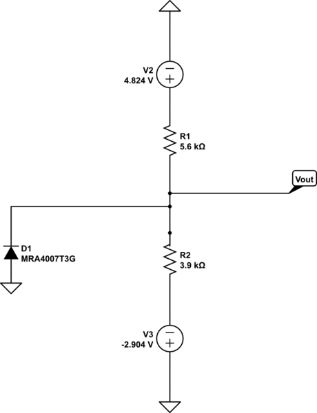
schematic

simulate this circuit – Schematic created using CircuitLab

I'm trying to figure out Vout. I need a formula that calculates Vout. Vout goes to an ADC. I have tried the voltage divider formula Vout=(Vs*R2)/(R1+R2), this doesn't give me the voltage that I measure. What steps do I need to complete to get the correct Vout? Thank you

\$\endgroup\$
8
  • 1
    \$\begingroup\$ amputate the "left leg" of your circuit and it will work fine. \$\endgroup\$
    – dandavis
    Commented Apr 26, 2017 at 20:20
  • 2
    \$\begingroup\$ Vout = 0V, you've shorted it \$\endgroup\$
    – Voltage Spike
    Commented Apr 26, 2017 at 20:20
  • 1
    \$\begingroup\$ Vout = 0V in your schematic. Is there a resistor missing? \$\endgroup\$ Commented Apr 26, 2017 at 20:21
  • \$\begingroup\$ The circuit has been built (not by me) already. This is what I have to work with. \$\endgroup\$
    – hfbroady
    Commented Apr 26, 2017 at 20:21
  • 1
    \$\begingroup\$ are you sure V3 is -2.904V? That means the voltage at the terminal connected to R2 is +2.904V! \$\endgroup\$
    – Curd
    Commented Apr 26, 2017 at 20:59

4 Answers 4

2
\$\begingroup\$

First off, you've shorted ground. Secondly you are using the wrong voltage divider equation.

If the bottom leg of the voltage divider is not zero, then you end up with a different equation:

$$ \frac{V_1-V_{out}}{R_1} = \frac{V_{out}- V_2}{R_2} $$ or $$V_{out} = \frac{R_1V_2+R_2V_1}{R_1+R_2} $$

if you set \$ V_2 \$ to 0v (ground) you get the standard form:

$$V_{out} = \frac{R_1*0+R_2V_1}{R_1+R_2} = \frac{R_2V_1}{R_1+R_2} $$

\$\endgroup\$
5
  • \$\begingroup\$ I know that it's not shorted to ground because when I measure the circuit with a volt meter I get 0.268V. When I use the formula that you gave me for both sources I get a Vout of 1.651V. Which is not what the circuit produces(0.268V)?? I did forget to place the diode on the left leg that is connected to ground \$\endgroup\$
    – hfbroady
    Commented Apr 26, 2017 at 20:39
  • \$\begingroup\$ The diode on the left leg is kind of important \$\endgroup\$
    – Voltage Spike
    Commented Apr 26, 2017 at 21:00
  • \$\begingroup\$ If you plug those numbers into the equation above, you get 0.268v because the diode does not turn on \$\endgroup\$
    – Voltage Spike
    Commented Apr 26, 2017 at 21:05
  • \$\begingroup\$ @laptop-- Yes I switched V's around when I did it the first time. I do get the correct answer now. Now I need to place that into my C code so that I can display the output onto a GUI that I made. Work work work. Thank you so much!!!! \$\endgroup\$
    – hfbroady
    Commented Apr 26, 2017 at 21:14
  • \$\begingroup\$ If the diode switches on, you'll get near 0.7V \$\endgroup\$
    – Voltage Spike
    Commented Apr 26, 2017 at 21:17
1
\$\begingroup\$

Your circuit, as others pointed out already, has ground tied to the node of interest. This pretty much determines the voltage there. (Well, this comment applied before you added the new diode.)

But let's say you have any number of Thevenin voltage source voltages with their series resistances, each tied to the same node where you want to find out the final voltage at that node. The general equation is:

$$\begin{align*} V_X&=\frac{\sum^N_{i=1}\left[V_i\cdot\prod^N_{j\ne i} R_j\right]}{\sum^N_{i=1}\left[ \prod^N_{j\ne i} R_j\right]}\\\\R_{X}&=\frac{\prod^N_{i=1} R_i}{\sum^N_{i=1}\left[ \prod^N_{j\ne i} R_j\right]} \end{align*}$$

Where \$V_X\$ is the resulting Thevenin voltage and \$R_X\$ is the resulting Thevenin resistance, looking into the node and related to the relevant ground reference.

For \$N=3\$, this results in:

$$\begin{align*} V_X&=\frac{V_1\cdot R_2\cdot R_3 + V_2\cdot R_1\cdot R_3 + V_3\cdot R_1\cdot R_2}{R_2\cdot R_3 + R_1\cdot R_3 + R_1\cdot R_2}\\\\R_{X}&=\frac{R_1\cdot R_2\cdot R_3}{R_2\cdot R_3 + R_1\cdot R_3 + R_1\cdot R_2} \end{align*}$$

Not much more to remember than that.


UPDATE because you edited your schematic:

Now, you've added a diode to your schematic.

Ignore the diode and apply the above formulas "as if" there was no diode connected in there. Replace all your sources and resistors with the new Thevenin voltage and resistance, as computed by the rules above.

Solve, now, a very simple voltage source, plus series resistor and diode, problem. Easy.
\$\endgroup\$
1
\$\begingroup\$

You should get 0.268 V, which you've said you do get.

You have a potential divider with 4.824 V at one end and -2.904 V at the other. So that's 7.728 V across the potential divider.

Your divider outputs (7.728 x 3900) / (5600 +3900) or 3.1725 V of the 7.728 V across it.

As the bottom of the divider is at -2.904 V, that's 3.172-2.904 = 0.268 V with respect to ground.

As the potential divider output voltage is positive, the reverse-biased diode has no real effect.

\$\endgroup\$
1
  • \$\begingroup\$ @TonyM-- Most of the comments about the shorting where added before that I place the diode on the left leg to ground. Thanks for the answer!! \$\endgroup\$
    – hfbroady
    Commented Apr 26, 2017 at 21:19
-1
\$\begingroup\$

Simple, as the output is clamped to -0.7 by the diode.

So you calculate Bout without the diode.

If the voltage is higher than -0.7v, the diode is reverse biased and voltage output is as calculated.

If the output is less than -0 7v, it will be clamped to -p.7v by the diode.

Solved.

\$\endgroup\$

Your Answer

By clicking “Post Your Answer”, you agree to our terms of service and acknowledge you have read our privacy policy.

Not the answer you're looking for? Browse other questions tagged or ask your own question.