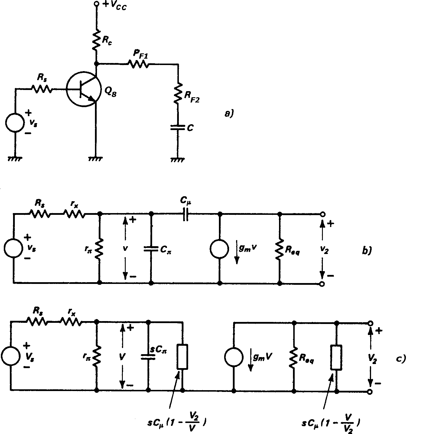
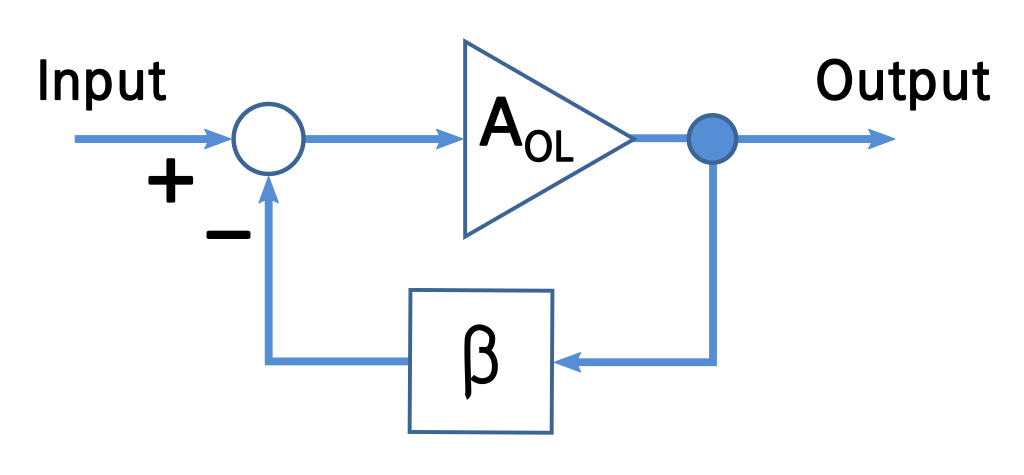
This circuit is made of one differential BJT transistor pair and voltage-amplification stage with negative feedback.
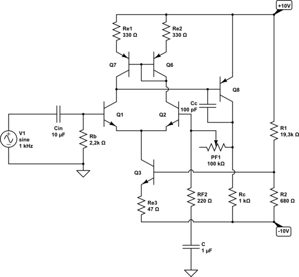
simulate this circuit – Schematic created using CircuitLab
About this circuit for DC conditions. Current through current source equals 2 mA and collector current through each differential transistor pair equals 1 mA. Current into base of VAS (Voltage Amplification Stage) is 20 uA and therefore collector current through it is 10 mA. For loop-gain ratio I firstly decided to be 11 (therefore PF1 was 2,2 kΩ) but then added 100 kΩ potentiometer to it to vary its gain in wide range.
As we speak about small signal analysis or AC conditions if this circuit, things here get a bit more stranger:
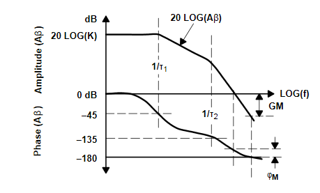
1.) Referring to this Bode plot here . The low frequency gain roll-off starts at already 2 kHz! Since I am interested mostly in designing audio amplifier this LF gain roll-off began here to quickly - I was aiming for at least 100 Hz or at 10 Hz of LF gain roll-off if possible. What should I do about it? I did put 100 pF compensation capacitor for improving amplifiers gain bandwidth. (I sampled some values here: (at 100 mVpp input sine) 2 kHz -> Vout = 1 Vpp, 1 kHz -> Vout = 0,88 Vpp, 100 Hz -> Vout = 0,18 Vpp)
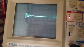
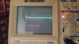
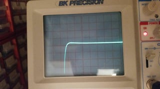
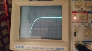
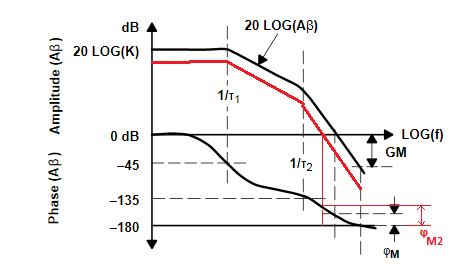
2.) Many of you know that, if the closed-loop gain of amplifier is high, that means we have smaller phase margin and greater influence of overshoot/undershoot and ringing at the output (we can see that from square input signal applied to it). And also, if the closed-loop gain of amplifier is low, that means we have larger phase margin (improved stability) and smaller influence of overshoot/undershoot and ringing, but the output signal has longer rise time.
Well, I did some measurements with my scope and function generator. And yes, I did see overshoot/undershoot, ringing, settling time and rise time within output (square) signal, when I was varying the closed-loop gain of amplifier in wide range of values. But there was something strange about it. When the closed-loop gain was high (around 500), I could saw slower rise time of output signal and when closed-loop gain was low (approx. 11), I clearly saw the presence of overshoot/undershoot and ringing within output signal - did I messed up things when I was learning about step response of amplifier or are things that concern overshoot, etc. showing up in reversed order?
3.) I was also trying to find high frequency gain roll-off of amplifier. At high closed-loop gain (around 500), the HF gain roll-off started at around 15 kHz to 20 kHz. But at low closed-loop gain (approx. 11), the HF gain roll-off didn't start at all - in fact the gain was slightly increasing with increasing the input frequency of signal (at 1 MHz it was still increasing!). So the first case seems pretty normal to me, but the second one seems rather extremely unusual than normal. Any ideas what is happening to this circuit at lower closed-loop gains? I thought that amplifier is very stable at low closed-loop gains but obviously not?

