3
\$\begingroup\$

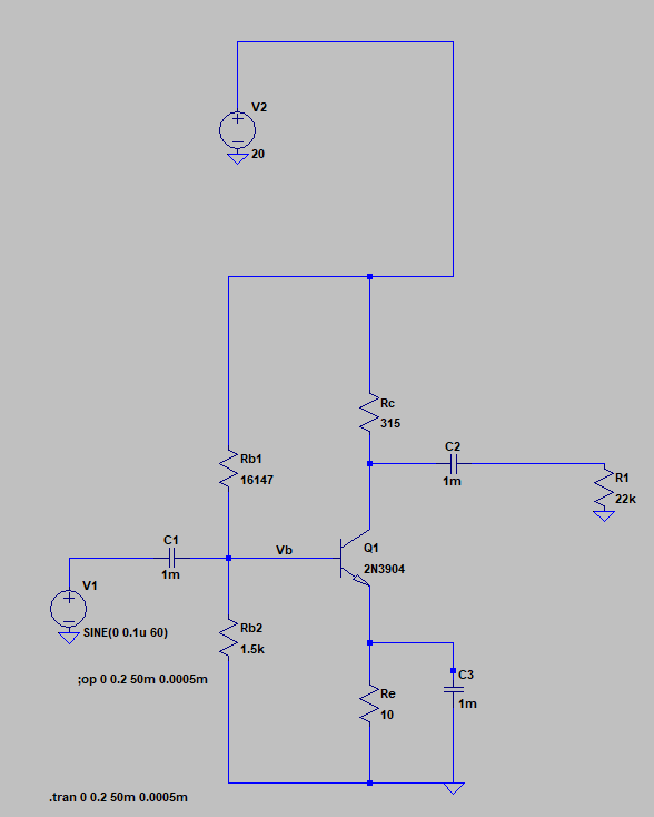
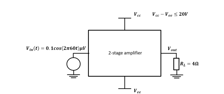
I need to design a 2 stage bjt amplifier that would amplify a 0.1uV waveform at least 100 times on a 4ohm load. How do I choose the proper stages for amplification? I was thinking about the most common CE-CC amplifier but I'm not sure if that's the best choice Amplifier

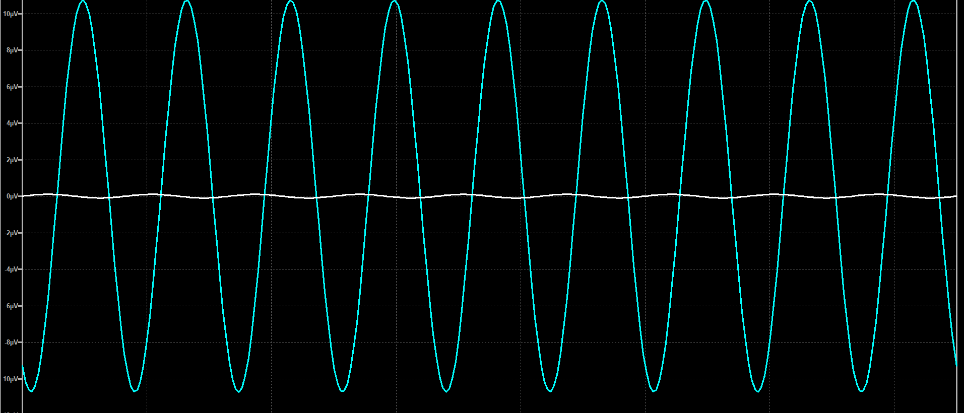
UPD: I made the 1st stage (CE) to have a gain of a little more than 100 but measured at 22kOhm load, Is that good enough to use with the CC amplifier?

CE CE output

\$\endgroup\$
1
  • \$\begingroup\$ CC is good choice for the 4 ohm load. Single stage CE with ac gain of 100 isn't unreasonable. \$\endgroup\$
    – AlmostDone
    Commented Apr 27, 2018 at 2:55

1 Answer 1

1
\$\begingroup\$

Consider this

schematic

simulate this circuit – Schematic created using CircuitLab

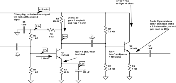
That 0.1uv (100 nanoVolt) input will be amplified 200X in Q1, then attenuated 2:1 by the voltage-divider of Q2's Rout and the 4 ohm load.

Assuming zero-source impedance, so Miller Effect has no effect on bandwidth, your gain-node time-constant will be 20pF * 200 ohm or 4,000 nanoseconds, thus bandwidth will be about 40MHz. Amazing.

Assuming the dominant random-noise contributor is rbb' of Q1, at 62 ohms, the noise density of 62 ohms is exactly 1 nanoVolt/rootHertz. A bandwidth of 40MHz increases the noise by 1nanoVolt * sqrt(40,000,000) = 1nV * 6,500 = 6.5 uV RMS referred-to-input random noise. The output noise, loaded by 4 ohms, will be 100X higher at 1.3 milliVolts RMS, about 9 milliVolts 6 sigma (2 ppm).

Your mileage may vary. I used no simulator in designing this.
\$\endgroup\$
4
  • \$\begingroup\$ So whats the point of C5 capacitor? The amplifiers we designed are usually biased with a simple two resistor voltage divider, so your biasing configuration confuses me a little \$\endgroup\$
    – Denis
    Commented Apr 27, 2018 at 3:26
  • \$\begingroup\$ The shown bias network is a very good one - it provides DC feedback for ensuring a stable bias point. It is the task of the capacitor C5 to allow only DC feedback. Frequencies above the corresponding corner frequency do not reach the base and, thus, cannot provide signal feedback with gain reduction. \$\endgroup\$
    – LvW
    Commented Apr 27, 2018 at 14:42
  • \$\begingroup\$ @LvW The lower corner is 0.16Hz * Av = 200 (or 32Hz). Is this easy to prove? \$\endgroup\$ Commented Apr 28, 2018 at 3:27
  • \$\begingroup\$ The cap value is 1 milliF. hence, the time constant is app. 1E-3*1E3=1 sec. That means wo=1rad/sec and fo=wo/6.28 \$\endgroup\$
    – LvW
    Commented Apr 28, 2018 at 10:24

Your Answer

By clicking “Post Your Answer”, you agree to our terms of service and acknowledge you have read our privacy policy.

Not the answer you're looking for? Browse other questions tagged or ask your own question.