1
\$\begingroup\$

I've just took for granted the fact that the input impedance of op-amp is high and output impedance is low.

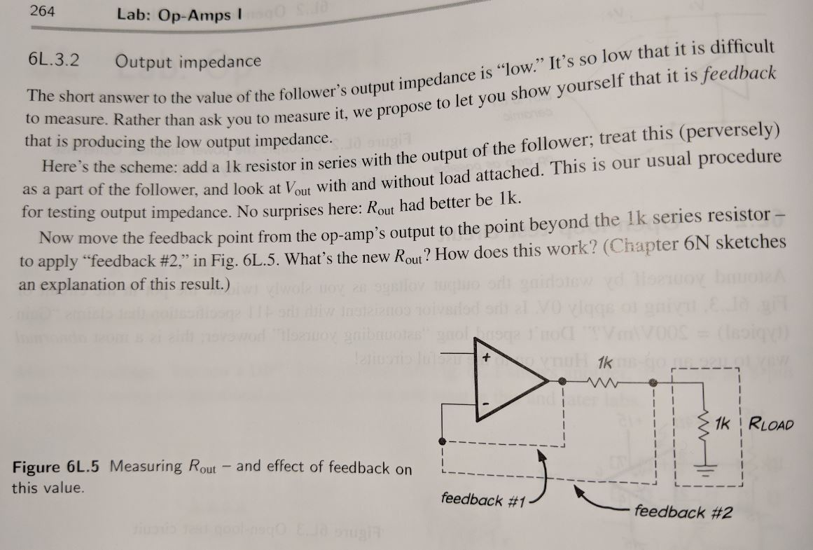
I was reading "the art of electronics" lab book and there is an exercise that asks you to measure the output impedance of an op-amp by having the negative input connected to the output (1) and after the 1k resistor (2) while having and removing the 1k load resistor.

It isn't clear to me how it allows them to measure the output impedance of the op-amp.

The only equation I could write down was with the load resistor in place and the negative input connected to the output of the op amp, I have the following equation

\$\displaystyle V_{out} = V_{in} \frac{R_{load}}{R_{load}+1k \Omega + Z_{out}} \$

I thought this would give you the output impedance of the op-amp.

I wasn't sure what the rest of the steps are for.

From(Learning the Art of Electronics: A Hands-On Lab Course)

enter image description here

\$\endgroup\$
3
  • \$\begingroup\$ Could you provide more detail or at least the chapter of the book where you read that? \$\endgroup\$
    – Undertalk
    Commented Oct 18, 2018 at 21:58
  • \$\begingroup\$ @Pitagoras so sorry. I forgot to include the image which I now posted \$\endgroup\$
    – Blackwidow
    Commented Oct 18, 2018 at 22:16
  • 1
    \$\begingroup\$ Another method is to hang a large capacitor on the output, and examine the frequency of oscillation. That tells you the output INDUCTANCE of the OpAmp. \$\endgroup\$ Commented Oct 19, 2018 at 3:34

2 Answers 2

1
\$\begingroup\$

The exercise is as follows.

In configuration feedback #1

  1. You measure V_out without R_load, with some high impedance voltmeter. Say you measure 5V
  2. Then you attach R_load. You get an output of 2.5V. You deduce the output impedance is 1k (which is expected because you have a 1k resistor in series with the load)

Then you switch to feedback #2

  1. You measure V_out without R_load, with some high impedance voltmeter. Say you measure 5V again
  2. Then you attach R_load. What do you get? Well, you get 5V. You are forced to conclude that the output impedance is 0
  3. Moreover, for any other load, 10K, 500R, 2K, you'll get 5V. Agree?

So, what happened? Feedback is producing the low output impedance. You can think the opamp is compensating the drop on the 1k resistor (raising the opamps output voltage).

\$\endgroup\$
8
  • \$\begingroup\$ Thanks for the response. Is V_out in feedback#1 always just after the op-amp and in feedback #2 always just after the 1k resistor? \$\endgroup\$
    – Blackwidow
    Commented Oct 19, 2018 at 14:54
  • \$\begingroup\$ If V_out is always the node right after the op-amp, im not sure how you can get 2.5V (half the first measurement) in case of feedback #1. I am trying to make sense of this in terms of voltage divider. \$\endgroup\$
    – Blackwidow
    Commented Oct 19, 2018 at 15:03
  • \$\begingroup\$ The measurement is ALWAYS over the R_load (or the voltmeter replaces it). Note that the purpose is to show that feedback produces ideally zero output impedance. The idea behind the case of feedback 2, is that you realize that the opamp itself can have an output impedance quite high, when you take the feedback path after that (now internal) output impedance, you still get zero output impedance, and this is due to feedback (as they wanted to show you). Note that in the case #2, you can think that the 1k resistor is inside the opamp. \$\endgroup\$
    – Undertalk
    Commented Oct 19, 2018 at 15:12
  • \$\begingroup\$ thank you again. But if we are ALWAYS measuring the voltage over the R_load, what should I do for the case where we don't have the R_load? (the first part of feedback#1 and feedback#2) \$\endgroup\$
    – Blackwidow
    Commented Oct 19, 2018 at 15:16
  • 1
    \$\begingroup\$ Thank you so much. I guess all my confusion stemmed from leaving it open vs shorting it \$\endgroup\$
    – Blackwidow
    Commented Oct 19, 2018 at 15:40
1
\$\begingroup\$

They are trying to show that the feedback mechanism compensates for any resistance on the output of the opamp driver stage (hence the term "perversely"). The opamp compensates for the new 1K ohm resistance by increasing it's drive so that the new feedback point again matches the positive input pin. You have to think of the (non-load) 1K resistor as having been internalized into the op-amp in this setup and thus compensated for the "horrible" 1K output impedance.

Bit of misnomer, I think they're measuring DC or a sine wave with no phase detection (depending on the frequency there may be visually notable change in the phase shift, indicating that the impedance actually has changed).

\$\endgroup\$

Your Answer

By clicking “Post Your Answer”, you agree to our terms of service and acknowledge you have read our privacy policy.

Not the answer you're looking for? Browse other questions tagged or ask your own question.