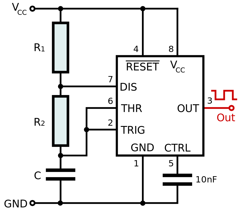
Pin 7 is the discharge pin. It's an open-collector type, so it can only sink current to ground. It cannot source any current, at all. (It only becomes active when one of the comparators determines that it is time to discharge the capacitor.)
If pin 7 were directly connected to the \$V_\text{CC}\$ power supply then it would be just fine, while pin 7 is inactive. In this case, the capacitor's charging rate would be determined only by \$R_2\$ and \$C\$ (since \$R_1\$ would effectively be \$0\:\Omega\$.)
However, as soon as pin 7 goes active and attempts to sink as much current as possible, the very low resistance of a short-circuit from pin 7 to \$V_\text{CC}\$ would mean that very high currents took place. These would be almost certainly be sufficient to vaporize the aluminum interconnects on the IC die somewhere near where pin 7 is bonded. So a direct connection from pin 7 to \$V_\text{CC}\$ is ill-advised because of the problem that occurs when pin 7 becomes active.
A resistor from pin 7 to \$V_\text{CC}\$ isn't entirely desirable as pin 7 not only has to work on discharging \$C\$ via \$R_2\$, but then pin 7 also must sink any current produced by \$R_1\$, too. However, that resistor is absolutely required in order to limit the current that pin 7 sinks, when active.
Pin 7 will have a specified current limit and this must be more than enough to cover the discharging current from \$C\$ as well as the excess current being supplied via \$R_1\$ when pin 7 is active. So that's something to watch for in the datasheet, too.
In general, directly tying pin 7 to \$V_\text{CC}\$ is a "bad thing" to do.

