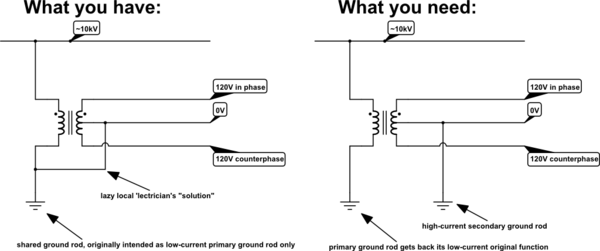
The situation I will describe is in a rural property that recieves only one wire from the power grid at 13.5kV. We have a single phase 25kVA transformer, that is shared with another house. On the primary side, one of the leads is connected to the wire from the power grid and the other to earth. On the secondary side is the standard 240V/120V 3 wire split-phase connection.
The problem encountered is that with almost no load (at the time of the testing I checked the neighbors electric meter and it only reported only 300W) the ground to to neutral voltage is 10V, one line to ground voltage is 130 and on the other line it's 110; note that the voltage between both hot wires is 240 and between each hot wire and neutral it's 120v. When a heavy load is aplied, we tested connecting a 4500W 240V water heater, the voltages were N-G:50V, L1-G: 170V, L2-G:70V and when the voltage between the ground of the circuit and an improvised ground was 5V. The measurements where taken both at the electric panel that is imediate to the electricity meter and on an electric socket inside the house. The values I wrote are rounded, as expected the L1-L2 voltage droped a small amount when the heater was on.
My conjecture based on the behavior of the voltage dependant on load and visual inspection of the wiring of the tranformer is that the same ground connection used for the primary side is used to ground the secondary side neutral and that the connection to ground used has a relatively high impedance. Those two things combined mean that the ground connection with too much impedance causes the IR voltage drop in the conductor between the transformer primary side neutral lead to the ground rod to be affecting the secondary side neutral voltage with respect to ground. The L1-L2 and L1,L2-N voltages are okay, even though the L1,L2-G and N-G voltage are dangerously wrong since the neutral to ground voltage is in phase with one of the lines and out of phase by 180º with the other line. Another important detail is that the electrician connected the house's circuit ground to the ground rod used for the transformer, wich explains why the circuit ground to improvised ground voltage was 5V when under load.
I wanted to ask here to know if my reasoning is posible or if there is some other explanation for the problem, since we contacted the electricity company and they have only, for the momment, sent an electrician and got nowhere, since they measured the L1-L2 and L1,L2-N voltages and saw they were okay and before they could do any further testing the electricity went out, so they had to leave (on that zone the electricity company has programmed blackouts, 6 hours of power/6 hours without power).

