1
\$\begingroup\$

enter image description here

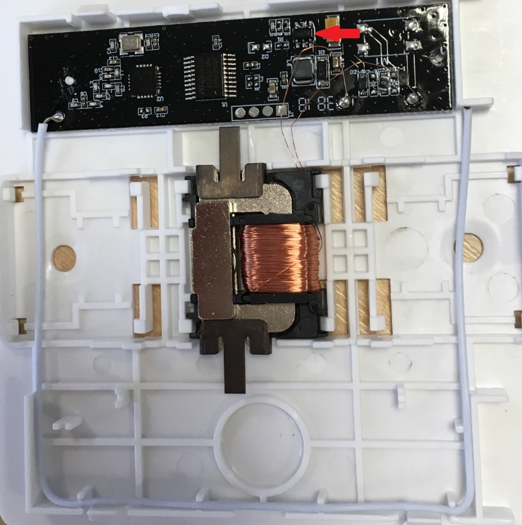
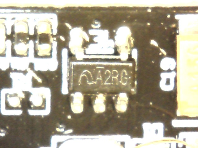
It is used to harvest kinetic energy from a switch to power an MCU for a short period of time which drives an RF transmitter. Looks like a linear regulator but I am unable to trace it back to the exact manufacturer and part number. Has anyone any vague idea? Thank you

I have taken a broader view photo of the PCB:

enter image description here

Unfortunately what Phil G has suggested could not be possible because the MCU is not fast enough to wake up and transmit an RF signal.

Googling around, the circuit on this PCB is very similar to what is described in this article, reason why I believe the sot23-5 is more like a regulator/buck that's powered up by the tantalum cap charged by the kinetic energy. Looks like the diode rectifier bridge as originally designed has been replaced with a half wave rectifier instead.

\$\endgroup\$

2 Answers 2

1
\$\begingroup\$

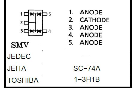
I'd guess it's a 1SS309, a rectifier array. It could be used to rectify the output of a generator coil attached to the trigger. Marking is listed as A2, but the additional digits could be a date/batch code enter image description here

\$\endgroup\$
2
  • \$\begingroup\$ Sorry Phil, it looks like there is already a full bridge rectifier made of discrete diodes on the PCB. I have added extra explanation in my post. Thanks for the suggestion. \$\endgroup\$
    – KLin
    Commented Mar 21, 2019 at 14:51
  • \$\begingroup\$ Now you show the device with the inductor and freewheel diode nearby it's obvious that it's a switching regulator. \$\endgroup\$
    – Phil G
    Commented Mar 21, 2019 at 16:18
1
\$\begingroup\$

Best hits I could find are N6200M5G-1.5 from NIKO-SEM and its twin brother APS1006 from APSemi.
Both have A2XY marking, where XY = Manufacturing Date Code.

But with the internal low side FET, diode D1 on the PCB should have a different function.

Guess you need to reverse engineer the IC's connections (which pin is connected to GND, which pin is connected to the inductor etc).

\$\endgroup\$
2
  • \$\begingroup\$ Thanks for the help! First, how did you find this part? Even Google does not know much about N6200M5G-1.5. Your guess is the most accurate so far, I have traced the connections and it corresponds to the adjustable version of this buck. However, the A2XY is for fixed outputs whilst the one on the PCB has got external voltage divider resistors exactly on the feedback pin. This makes me confused. Any more thoughts? Thank you! \$\endgroup\$
    – KLin
    Commented Mar 25, 2019 at 15:43
  • \$\begingroup\$ Using search engines ending up at this very useful site: s-manuals.com/smd/63 \$\endgroup\$
    – Huisman
    Commented Mar 27, 2019 at 21:19

Your Answer

By clicking “Post Your Answer”, you agree to our terms of service and acknowledge you have read our privacy policy.

Not the answer you're looking for? Browse other questions tagged or ask your own question.