1
\$\begingroup\$

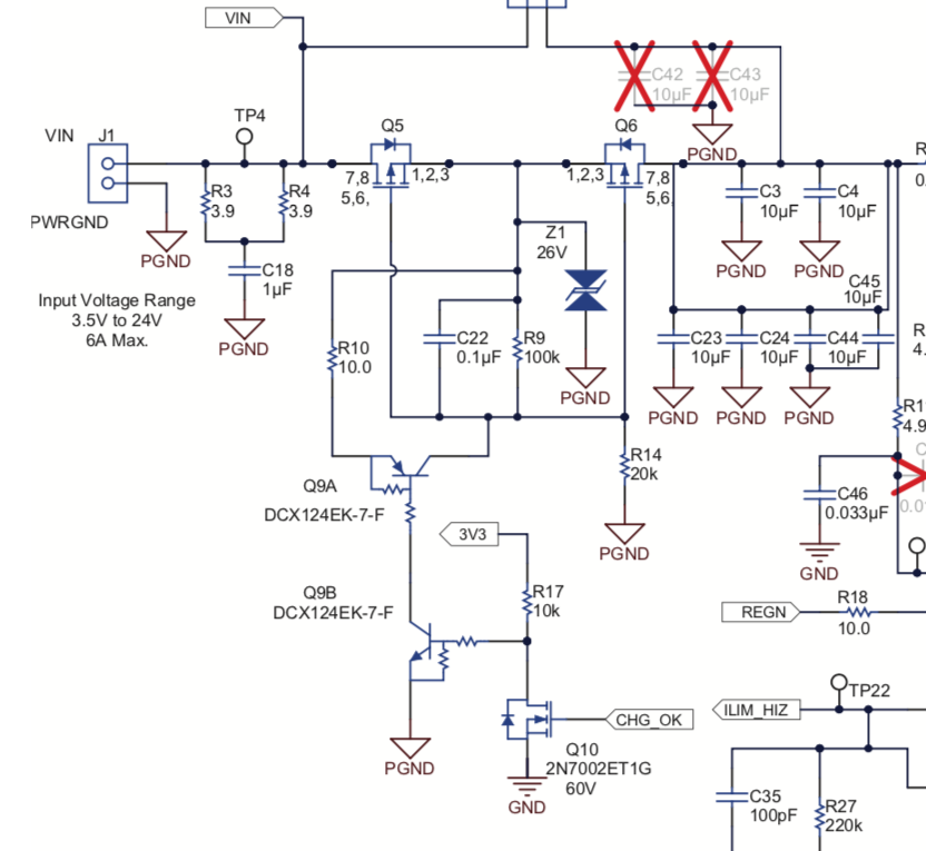
I am analysing the an eval board circuit for a battery charger IC which has the following inrush control circuit.

er

Question 1: I understand that C22 is used to "slow start" Q6 limit inrush current into C3,C4,C23,C24,C44. Signal CHG_OK goes high, when a power source is detected at J1 (12V). With CHG_OK high, Q10, Q9B and Q9A are turned on. I don't understand resistor R10 because if Q9A is on, ~12V are applied on Q6 gate, which will keep Q6 closed. How does this inrush control circuit work?

Question 2 Why are there several capacitors (C3,C4,C23,C24,C44) and why can't they be replaced with just one large capacitor?

\$\endgroup\$
1
  • \$\begingroup\$ The multiple capacitors are probably decoupling multiple chips, or multiple power pins on one chip, and will be placed close to those power pins. \$\endgroup\$
    – Hearth
    Commented Jul 28, 2019 at 14:46

1 Answer 1

1
\$\begingroup\$

1: When CHG_OK is high the R10 is open-circuit and both series pass FETs conduct with a slow turn-on time. When this signal goes low R10 shunts Vgs quickly as the 0.1uF is discharged in 1us then FETs are shut off.

2: low ESR caps of 10uF have an inherent \$\tau=\$ESR*C<=10us constant in any given family at some Vdc rating and size.

  • High ESR or General Purpose has a τ>200us thus high ESR
  • you can reduce the ESR by using parallel Caps of the same size but not by increase C value unless the sub-miniature SMD size is also substantially increased. However, experience dictates that shunting smaller low ESR Caps improves results immensely as the length of the cap also increases inductance 0.5nH/mm which then reduces the Series Resonant Frequency (SRF) which increase rise-time of current.

Expect a typical Panasonic 10uF low ESR to be < 1 Ohm and 10 in parallel = 0.1 Ohm ESR which thus reduces voltage rise from dV=I*(ESR+dt/C)

\$\endgroup\$
2
  • \$\begingroup\$ 1: I made a mistake. Of course, when CHG_OK is high, then Q9A and Q9B are OFF. 2: understood. Is there any "best practice" on how to design these decoupling capacitors in terms of how many should be put in parallel? \$\endgroup\$ Commented Jul 28, 2019 at 15:13
  • \$\begingroup\$ Yes but you need to know what your operating frequency is and current thus Impedance or dV/dI \$\endgroup\$
    – D.A.S.
    Commented Jul 28, 2019 at 15:13

Your Answer

By clicking “Post Your Answer”, you agree to our terms of service and acknowledge you have read our privacy policy.

Not the answer you're looking for? Browse other questions tagged or ask your own question.