1
\$\begingroup\$

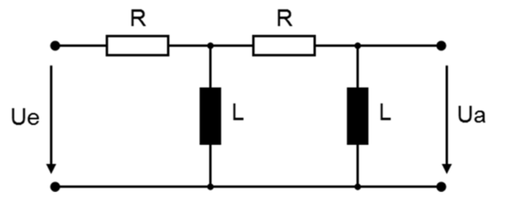
I have the following circuit:

enter image description here

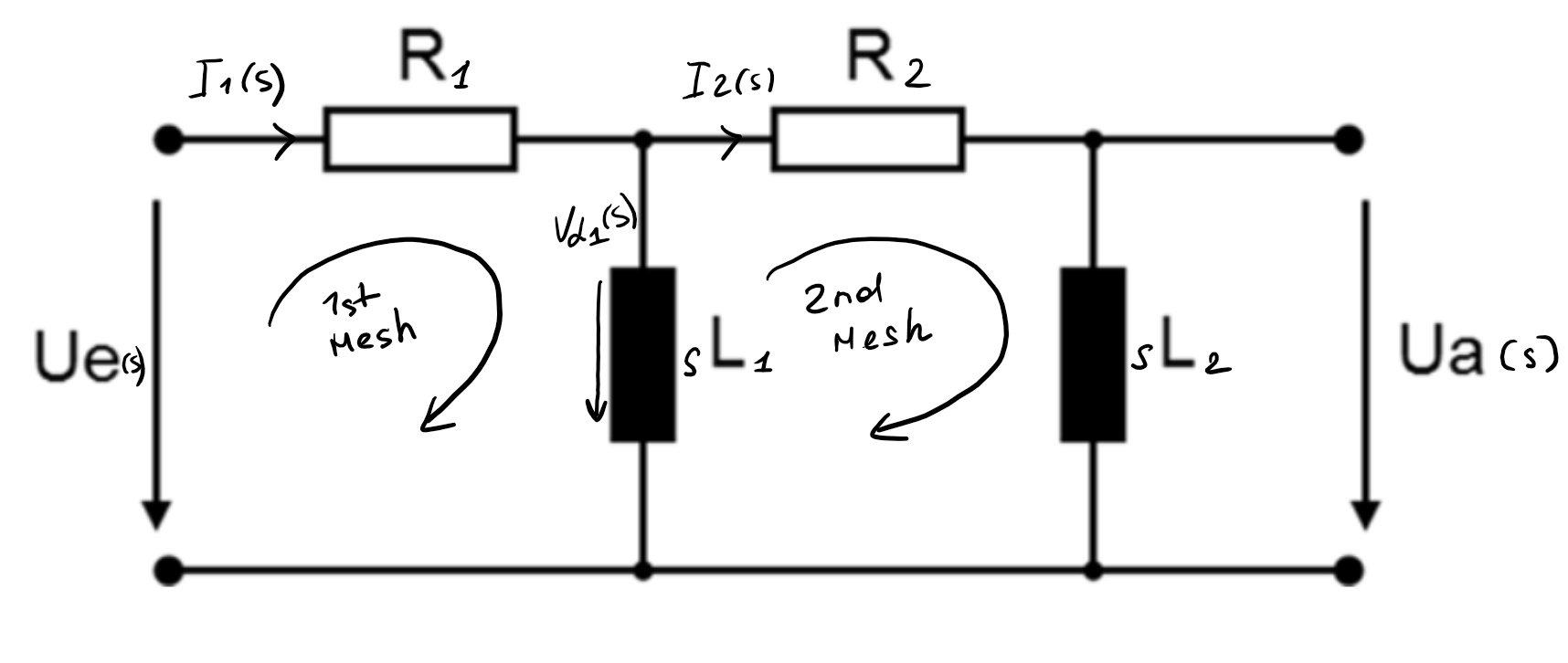
I have to find the transfer function by using mesh analysis. First of all I used the Laplace transformation.

enter image description here

Although I saw some similar exercises, I don't really see what I can get out of the mesh equations.

1st Mesh $$V(s) - I_{1}(s)R_1 - V_{L_1}(s) = 0$$

2nd Mesh $$V_{L_1}(s) - I_{2}(s)R_2 - I_{2}L_{2}s = 0$$

Also I assumed that $$V_{L_1}(s) = sL_{1}(I_{1}(s) - I_{2}(s))$$

\$\endgroup\$
1
  • \$\begingroup\$ I'd recommend checking by doing a triangle->star transformation (Delta-Y transformation) on your 2nd mesh. It greatly simplifies the problem. Remember: there's no current leaving the circuit at the right hand side. \$\endgroup\$ Commented Aug 12, 2019 at 11:49

3 Answers 3

1
\$\begingroup\$

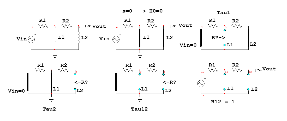
This transfer function can be solved without writing a single line of algebra while going straight to the point with a low-entropy expression. I will be using the fast analytical circuits techniques or FACTs as described in the book I published in 2016. The principle is truly simple and applies well to passive circuits of any order: determine the time constants of the circuit when the excitation is zeroed (the input is shorted with a voltage source) and the output is nulled. The below drawing shows the steps which consists of "looking" through each energy-storing element and determining the resistance \$R\$ you "see". That resistance is then part of the time constants we want, \$\tau=\frac{L}{R}\$ in our case.

The below drawing shows the adopted steps. With some habit, you can omit the drawings and write the time constants directly but it is good to have these pictures as you could come back to any of them and fix one in case a deviation would be observed in the end.

enter image description here

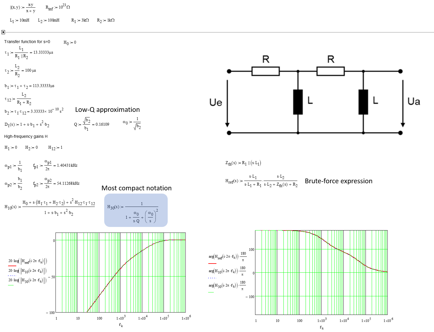
You start with \$s=0\$ in which all inductors are put in their dc state, implying a signal path shorted twice: you have a double zero at the origin and the dc gain \$H_0\$ is obviously zero. Then you turn the excitation off and a 0-V voltage source is replaced by a short circuit. That is what the drawings reflect and you just have to inspect the sketch to infer the resistance value. Truly fast and easy. Then, once the natural time constants are determined, calculate three gains \$H\$ in which each inductor is alternately replaced by its high-frequency equivalent component (an open circuit) while the second inductor is a short. Following this rule, gains \$H_1=H_2=0\$ while the only valid gain is when both inductors are open-circuited (\$s\$ approaches infinity) and we have \$H_{12}=1\$. Assemble the whole thing in a Mathcad sheet and, voilà, the curves show up with the final transfer function assembled in the most compact form, \$H_{30}\$:

enter image description here

Because the roots are real, you can apply the low-\$Q\$ approximation and unveil a format having a inverse pole in the denominator making the transfer function extremely compact. The leading term should be the high-frequency gain which is 1 but would be lower is one chose to load the circuit with a resistance.

\$\endgroup\$
0
\$\begingroup\$

Well, I'll present a method that I like to use.

We have that:

$$\mathcal{H}\left(\text{s}\right):=\frac{\text{V}_\text{o}\left(\text{s}\right)}{\text{V}_\text{i}\left(\text{s}\right)}\tag1$$

Now, we know that:

$$\text{V}_\text{i}\left(\text{s}\right)=\text{I}_\text{i}\left(\text{s}\right)\cdot\left(\text{R}+\frac{\text{sL}\cdot\left(\text{R}+\text{sL}\right)}{\text{sL}+\text{R}+\text{sL}}\right)\tag2$$

And:

$$\text{V}_\text{o}\left(\text{s}\right)=\text{I}_\text{o}\left(\text{s}\right)\cdot\text{sL}=\text{I}_\text{i}\left(\text{s}\right)\cdot\frac{\text{sL}}{\text{sL}+\text{R}+\text{sL}}\cdot\text{sL}\tag3$$

So:

$$\mathcal{H}\left(\text{s}\right):=\frac{\text{V}_\text{o}\left(\text{s}\right)}{\text{V}_\text{i}\left(\text{s}\right)}=\frac{\text{I}_\text{i}\left(\text{s}\right)\cdot\frac{\text{sL}}{\text{sL}+\text{R}+\text{sL}}\cdot\text{sL}}{\text{I}_\text{i}\left(\text{s}\right)\cdot\left(\text{R}+\frac{\text{sL}\cdot\left(\text{R}+\text{sL}\right)}{\text{sL}+\text{R}+\text{sL}}\right)}=\frac{\text{s}^2\text{L}^2}{\text{R}^2+\text{s}\left(\text{sL}^2+3\text{LR}\right)}\tag4$$

So, let's say that \$\text{R}=\text{L}=1\$, than we get:

$$\mathcal{H}\left(\text{s}\right)=\frac{\text{s}^2}{\text{s}^2+3\text{s}+1}\tag5$$

And so for the frequency response, we are looking at:

  • The magnitude: $$\left|\mathcal{H}\left(\text{j}\omega\right)\right|=\frac{\omega^2}{\sqrt{\omega^4+7\omega^2+1}}\tag6$$
  • The phase: $$\arg\left(\mathcal{H}\left(\text{j}\omega\right)\right)=\begin{cases} 0\space\space\space\space\space\space\space\space\space\space\space\space\space\space\space\space\space\space\space\space\space\space\space\space\space\space\space\space\space\space\space\space\space\space\space\space\text{when}\space\space\space\omega=0\\ \\ 0\space\space\space\space\space\space\space\space\space\space\space\space\space\space\space\space\space\space\space\space\space\space\space\space\space\space\space\space\space\space\space\space\space\space\space\space\text{when}\space\space\space\omega=1\\ \\ \arctan\left(\frac{3\omega}{\omega^2-1}\right)\space\space\space\space\space\space\space\space\space\space\space\space\space\space\text{when}\space\space\space\omega>1\\ \\ \frac{\pi}{2}+\arctan\left(\frac{\left|\omega^2-1\right|}{3\omega}\right)\space\space\space\space\space\text{when}\space\space\space0<\omega<1 \end{cases}\tag7$$
\$\endgroup\$
1
  • \$\begingroup\$ could you further explain the "Now, we know that" part? Also, an edit happened and now the resistors and inductors are not equal in value. At last, the "So, let's say that R=L=1, than we get" and following part go way out of what is being asked. \$\endgroup\$
    – jDAQ
    Commented Aug 16, 2019 at 3:23
-1
\$\begingroup\$

The solution in the Laplace Domain, with zero initial conditions, requires to solve the circuit simply replacing the inductors impedance effect \$v(t)=L\frac{di(t)}{dt}\$ with \$V(s)=sLI(s)\$

The circuits expressions are:

$$V_1=R_1I_1+sL_1(I_1-I_2)$$

$$sL_1(I_1-I_2)=R_2I_2+sL_2I_2$$

$$V_2=sL_2I_2$$

They can be simply rearranged as:

$$I_1={V_1+sL_1I_2 \over R_1+sL_1}$$

$$I_2={sL_1I_1 \over R_2+sL_2+sL_1}$$

From here, \$I_1\$ and \$I_2\$ can be obtained:

$$I_2={V_1sL_1 \over R_1+sL_1}{1 \over (R_2+sL_2+sL_1)-(sL_1)^2}$$

$$I_1={V_1\over R_1+sL_1}{1+(sL_1)^2 \over (R_1+sL_1)((R_2+sL_2+sL_1)-(sL_1)^2)}$$

And finally, the transfer function is calculated as:

$$V_2/V_1=1-R_1I_1/V_1-R_2I_2/V_1$$

\$\endgroup\$
3
  • \$\begingroup\$ The final equation is not a TF - it has V1 on the right hand side. This question looks like homework, btw, so only guidance should be given. Finally, a TF means that initial conditions are zero. Apart from that, everything's ok! \$\endgroup\$
    – Chu
    Commented Aug 12, 2019 at 16:40
  • \$\begingroup\$ 1. There is not any V1 on the right hand side. 2. The question is not completely solved, so this is actually only a guidance. 3. It has been indicated that no IC are required. \$\endgroup\$
    – Brethlosze
    Commented Aug 12, 2019 at 21:55
  • \$\begingroup\$ Thank you so much for you help! I was trying to find I2 - I took the rearranged equation for I2 (4th equation in your post) and substituted the I1 with the 3d equation(rearranged I1). But I ended up getting I2 on the both sides, i don't understand how you eliminated I2 on the right side and got the 5th equation.. I would be very very grateful if you could point out my mistake. \$\endgroup\$
    – vb_2004
    Commented Aug 13, 2019 at 5:07

Your Answer

By clicking “Post Your Answer”, you agree to our terms of service and acknowledge you have read our privacy policy.

Not the answer you're looking for? Browse other questions tagged or ask your own question.