0
\$\begingroup\$

I am trying to design a PCB circuit in altium designer.

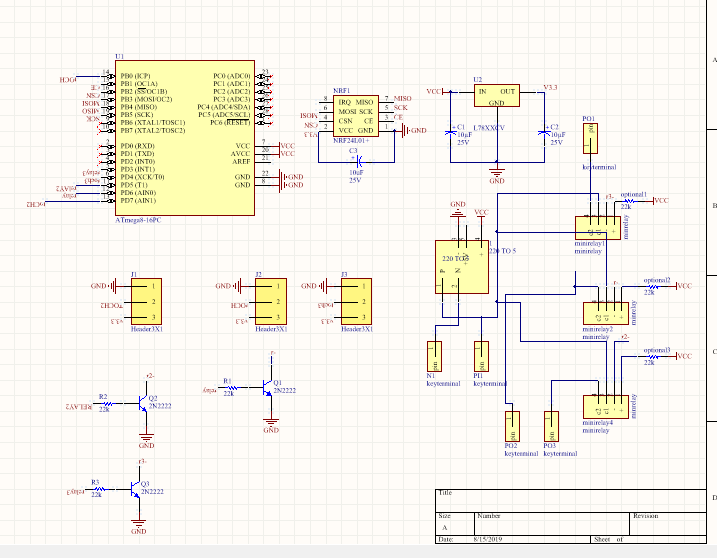
My circuit consists of one ATmega8a, one NRF24l01 and three magnetic relays (mini relay 12V MPR-S-112-A.)

I want to set the trace width to 0.5mm (except power circuit.)

Is that correct ?

If it is wrong, what width should I use?

circuit

\$\endgroup\$
1
  • 1
    \$\begingroup\$ Saturn PCB has a handy tool for all sorts of (these things) Link \$\endgroup\$
    – Tyler
    Commented Aug 15, 2019 at 11:03

2 Answers 2

1
\$\begingroup\$

0.5mm is 20mil, right? That's fine for most work at lowish frequencies.

\$\endgroup\$
3
  • \$\begingroup\$ I know this is an old post. But 20mil is NOT 0.5mm. It's 0.508mm. Not a big deal for trace width, maybe. But a real big deal for a 100 pin tqfp with 0.5mm pitch. The error across 25 pins accumulates to 0.2mm. I have just been burned by this - The engineer who created the footprint worked in Imperial units, and also used 20mil=0.5mm \$\endgroup\$ Commented Sep 27, 2023 at 11:24
  • \$\begingroup\$ @StephenCasey If you try putting 0.5mm -- or 20mil -- width traces into a 0.5mm pitch footprint, it won't exactly matter... neither one is going to connect to any of the pads! \$\endgroup\$ Commented Sep 27, 2023 at 12:44
  • \$\begingroup\$ He has specifically asked for tracewidth, and not a pad layout. Yes, 20mil = 0.508mm. And no - there's no "100 pin tqfp" in the schematic shown \$\endgroup\$ Commented Oct 24, 2023 at 6:21
1
\$\begingroup\$

you can use these guidelines Guidelines or similar as a reference for a decent layout. On the right hand side of the GUI, you will find track width graphic.

\$\endgroup\$

Your Answer

By clicking “Post Your Answer”, you agree to our terms of service and acknowledge you have read our privacy policy.

Not the answer you're looking for? Browse other questions tagged or ask your own question.