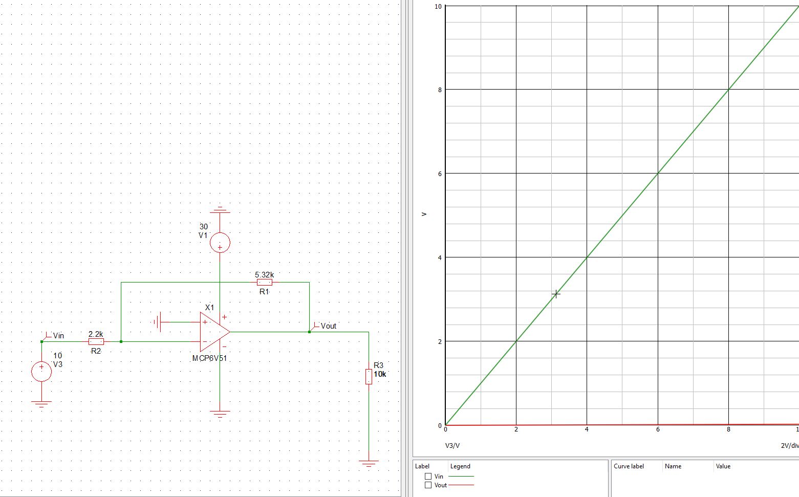
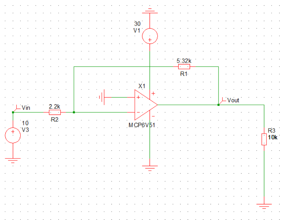
I am trying to build a circuit which is controlled from an analog input signal Vin to produce a -24V signal with >50mA output. My analog card can only produce ~10mA, therefore I generate the signal using an Op-Amp. I used the analog simulation tool from Microchip (MINDI) and the simulation result differs from my hand calculation.

The circuit represents the standard layout of a inverting amplifier. I removed most of filter capacitors and other resistors from the design guideline. Building a non-inverting amplifier with the same principle gives the correct results. Is there a bug in the calculation of the simulation or does my circuit has a significant error?

