0
\$\begingroup\$

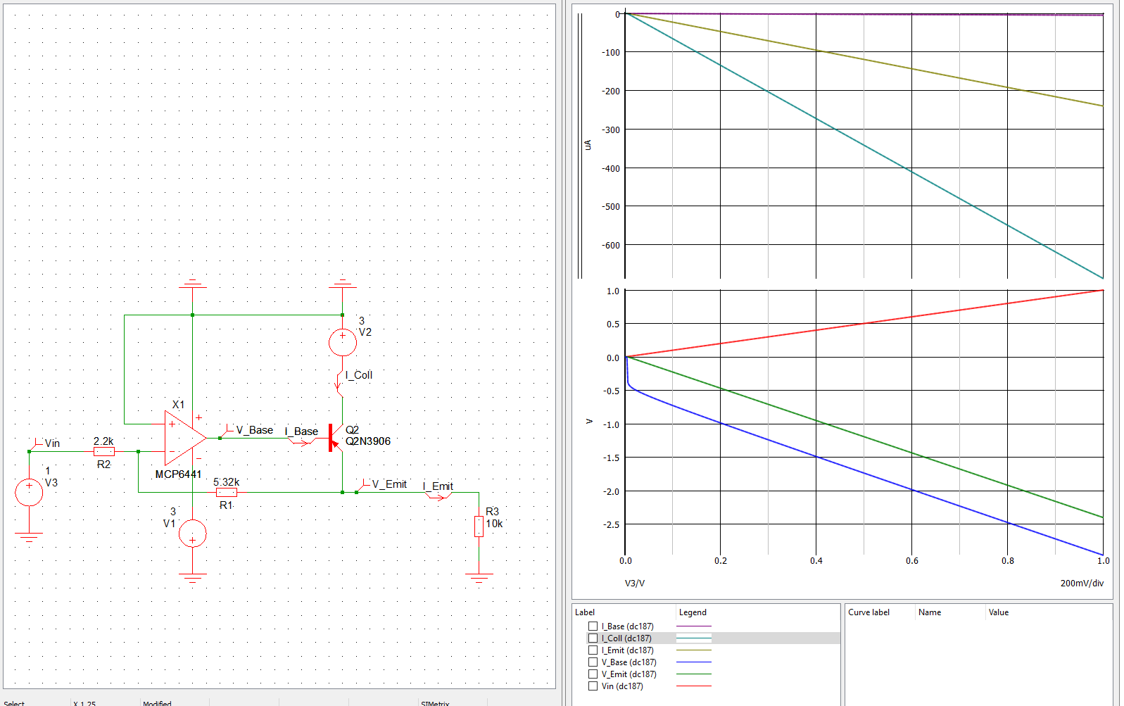
Following up on this question I redesigned my circuit with the suggestions from the comments (see comments from @Andy_aka). I want to drive the output of the opamp between 0-24V with an Vin = 0-10V. I also need to draw currents arround 50mA. At low input voltages the power consumption of the opamp would probably damage the device. With a voltage follower I want to draw the current directly from my power source. I found some circuits on the internet and tried implementing them into my design

enter image description here

The voltages seem to be correct for the base and the load (R3). The current from the base is still higher than the current on the load. Should the main draw not come directly from the power source and not the output from the opamp?

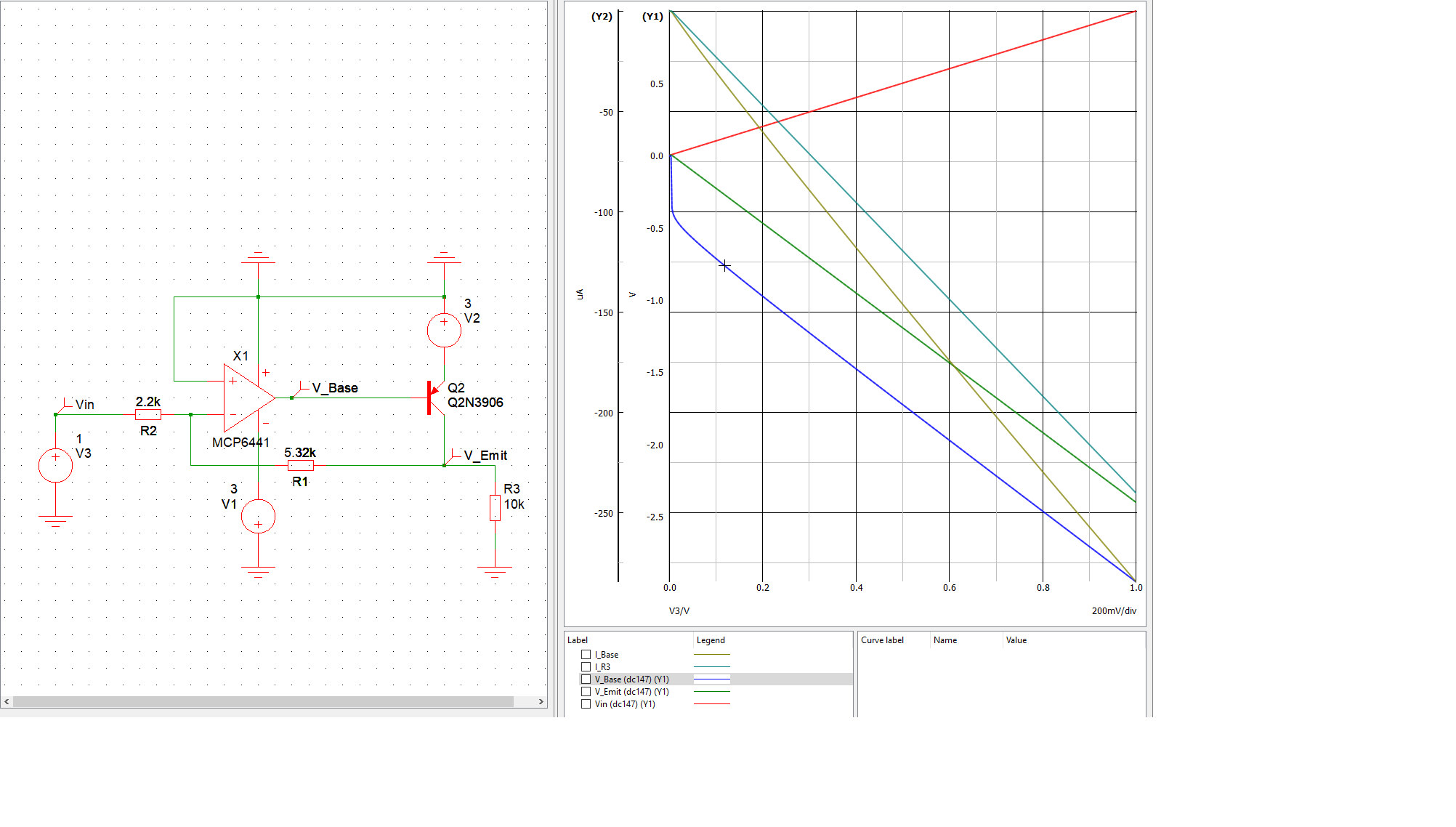
UPDATE: I switched the direction of the transistor per @James suggestion and the current in the base is greatly reduced, where the Emitter (load) side draws the current from the collector. I also redraw the result window

opamp_voltagefollower_corr

\$\endgroup\$
4
  • 1
    \$\begingroup\$ Swap the emitter and collector over with each other. Watch out for the common mode input limit \$\endgroup\$
    – user173271
    Commented Jan 27, 2020 at 13:55
  • \$\begingroup\$ That op-amp is only good for a 6 volt rail and you need at least 25 volts. Is the previous question done with now? \$\endgroup\$
    – Andy aka
    Commented Jan 27, 2020 at 14:05
  • \$\begingroup\$ Yes. I tried to scale the problem from 30V->3V since I can not find compatible devices in the MINDI library \$\endgroup\$
    – v3xX
    Commented Jan 27, 2020 at 14:19
  • \$\begingroup\$ If you're having trouble finding a suitable op amp then, as an alternative solution, you could add a +5V supply to the op amp (non-inverting input still connected to ground). Then you could use a common op amp such as the LM358 which has a possible common mode input range to within 1.5V of the positive supply. Also the LM358's output will swing between the negative supply and to within 1.5V of the positive supply. \$\endgroup\$
    – user173271
    Commented Jan 28, 2020 at 9:48

1 Answer 1

1
\$\begingroup\$

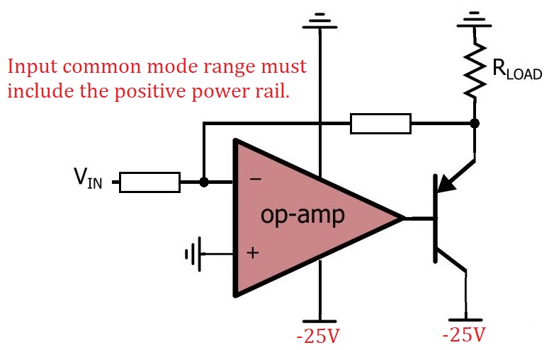
This is the sort of circuit you need to be considering: -

enter image description here

Of importance is that the op-amp's input common mode range MUST include the positive ground rail. This makes the choice of op-amp more difficult but there will be devices that fit the bill.

\$\endgroup\$
1
  • \$\begingroup\$ Thanks for the visualization. I updated my original answer with @James suggestions. On first glance the circuit now behaves like it should (small base current, high current on the load). Now I have to dig in and try to understand whats happening in detail. \$\endgroup\$
    – v3xX
    Commented Jan 27, 2020 at 14:33

Your Answer

By clicking “Post Your Answer”, you agree to our terms of service and acknowledge you have read our privacy policy.

Not the answer you're looking for? Browse other questions tagged or ask your own question.