1
\$\begingroup\$

I've a simple circuit where I need to detect AC voltage presence via a microcontroller (ESP32).

The ESP32 is a 3.3V device, and requires (worst case) 2.8V to consider a logical one on a GPIO.

I'm using a photocoupler (TLP290) for this. Such photocoupler requires at least 0.5mA to start conducting (the CTR for such a low diode current is only 70% typically).

On the AC side, I'm currently using two 1/4W resistors in SMD. (See top circuit). For the configuration shown, I'm expecting 0.7mA in the circuit (input is 230Vac at 50Hz), so the resistors will dissipate ~90mW each. In case of overvoltage, with 280Vac, they'll dissipate ~130mW each.
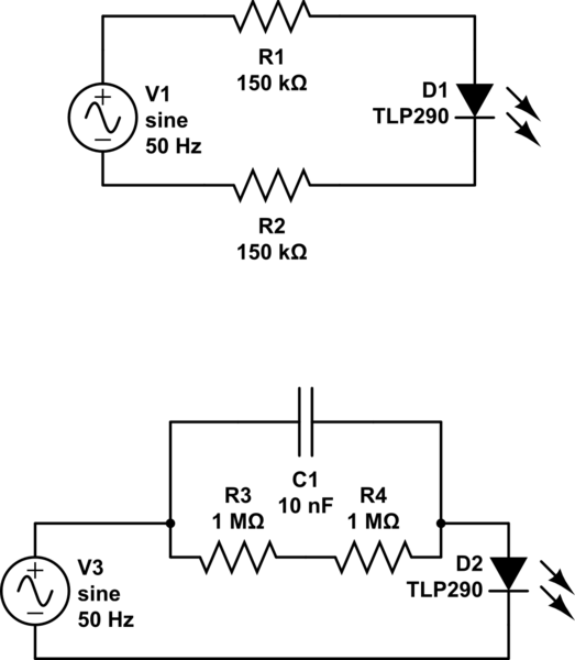
schematic

simulate this circuit – Schematic created using CircuitLab

I think such power might cause issues (like local high temperature on the PCB) so I'm trying to replace the basic resitors by a more complex RC filter so that the impedance is close to what I want at 50Hz, but less power is dissipated in the resistors.

See the bottom circuit for an example implementation. In such circuit, the impedance of the RC filter is ~300kOhm at 50Hz so the same current flows in the circuit, but then the power dissipated in the resistors is now only 12mW.

I understand I must use a X rated capacitor for this case (I'm not connected to ground in that case), but I don't understand which of X1 or X2 type I must use.

I'd like to avoid using film capacitors here, since they only exist in through hole version, and I'd like to use SMD capacitors here (15nF does exists in SMD in 2010 package).

note: I haven't found an optocoupler in the circuit drawing software on this site, so please consider the D1 or D2 diode as the 2 inputs diodes of the AC photocoupler.

\$\endgroup\$
8
  • 1
    \$\begingroup\$ Besides your worries about power dissipation (that I'll not address in this comment), you should be concerned about the reverse voltage in the optocoupler's diode, at the negative cycles of AC. You could use a 1N4007 diode reversed in parallel (be aware that the optocoupler will flash at 25 Hz), or you could use a full bridge rectifier before the optocoupler's LED. \$\endgroup\$
    – mguima
    Commented Feb 1, 2020 at 19:46
  • \$\begingroup\$ The schematic here is wrong (I was not able to find a suitable symbol in this site's software). The optocoupler is a AC one, with two diodes in opposite direction (both emit light to trigger the phototransistor), so it's already accounting/dealing for/with reverse voltage. \$\endgroup\$
    – xryl669
    Commented Feb 1, 2020 at 19:50
  • \$\begingroup\$ You must add a series resistor, otherwise there is little to limit the current in case of power applied at the peak of the mains or in case of a transient on the mains. \$\endgroup\$ Commented Feb 1, 2020 at 19:52
  • 1
    \$\begingroup\$ Imagine you switch the input on at the peak of the 230V mains. 325 volts will suddenly appear across some combination of the capacitor ESR, the mains inductance, whatever resistance may be there, and the LED. The current will be hard to predict, but definitely above the absolute maximum rating of the LEDs. \$\endgroup\$ Commented Feb 2, 2020 at 0:30
  • 1
    \$\begingroup\$ @SpehroPefhany, The TLP290 supports up to 1A as input pulsed current (during 0.1ms), and up to 50mA in RMS current, so it would "burn" only if the resistance in the path is less than 6.5 kOhm. I don't get how that could happen, but I can put a 6.8kOhm in serie with the RC filter to prevent this, if this is what you meant. \$\endgroup\$
    – xryl669
    Commented Feb 2, 2020 at 13:19

1 Answer 1

1
\$\begingroup\$

This question is very old, but I think the answer might still help others. So here it is:

Choosing between Y and X capacitor

I assumed in the question that a X capacitor should have been selected here. X capacitor have the "feature" of failing to short, meaning that if/when they fail, they'll short their connections. Usually, this is ok when they are mounted between Line and Neutral, since the fuse or circuit breaker will trip when it happen and protect the rest of the installation. The device has to be replaced before the circuit is re-engaged.

A Y capacitor, on the opposite, fails to open circuit. This is dangerous when mounted between a Line and Neutral, since upon failure, they don't protect the device down the nets anymore. They are usually recommended between Neutral and Ground or between Line and Ground. In that case, if they fail, they are isolating the ground from the device so there's a risk of electric shock that can be mitigated by a RCBO.

In the circuit above, a Y capacitor should have been used, because if it fails, the 2 MΩ net will take precedence and limit the current to almost zero (not enough for the photocoupler's LED to trigger). Said differently this failure would have prevented the system to detect the presence of main, but overall, it would have continued to work. Fixing the device would only require to replace the Y capacitor.

Using a X capacitor here means that a failure will short the photocoupler's LED directly between Line and Neutral, likely burning the photocoupler and tripping the circuit breaker. In case of failure, fixing the device would have required to replace both the capacitor and the photocoupler.

Difference between X1 and X2 (and X3)

Although not really required anymore, let's answer the question. The difference in the X capacitor is mainly their ability to handle larger peak voltage. Since they are mounted between Line and Neutral, they are usually subjected to short, but intense, peak voltage.

X3 is the least tolerant capacitor to peak voltage pulses. It can fails with only 1200 V. This peak seems high, but it's very low and it happens very often. Typically, no one use X3 capacitors.

X2 supports peaks up to 2500 V. That's the capacitor required if you install your device in a home plugs. They are designed, in IEC 60664-1 as category 2. Unless you're dealing with industrial or power supply electronic, that's what to choose.

X1 supports peaks up to 4000 V. They are usually used in higher voltage installation (industrial or close to the voltage supply).

Can I replace one capacitor by another?

You can use a Y2 capacitor in place of a X2 capacitor temporarily (it'll unprotect the net upon failure) but never the opposite.

Also, if the peak voltage is a concern, you should use a metal oxide varistor across the L/N nets to limit the peak voltage to 2500 V and be able to use your X2 capacitor.

\$\endgroup\$

Your Answer

By clicking “Post Your Answer”, you agree to our terms of service and acknowledge you have read our privacy policy.

Not the answer you're looking for? Browse other questions tagged or ask your own question.