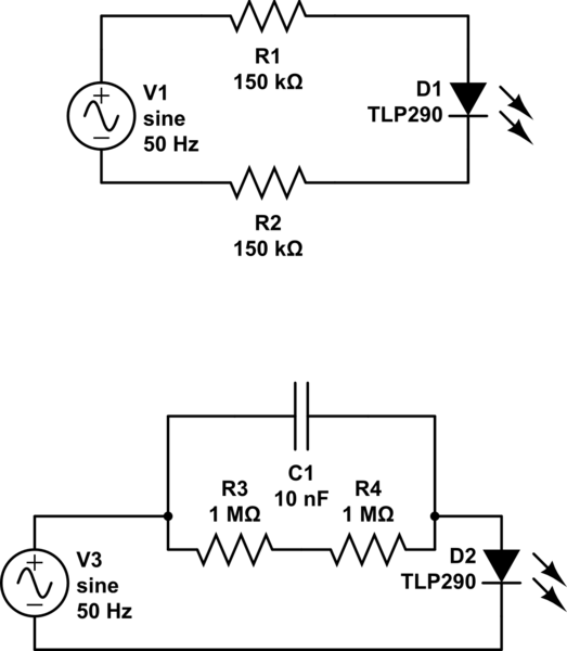
I've a simple circuit where I need to detect AC voltage presence via a microcontroller (ESP32).
The ESP32 is a 3.3V device, and requires (worst case) 2.8V to consider a logical one on a GPIO.
I'm using a photocoupler (TLP290) for this. Such photocoupler requires at least 0.5mA to start conducting (the CTR for such a low diode current is only 70% typically).
On the AC side, I'm currently using two 1/4W resistors in SMD. (See top circuit). For the configuration shown, I'm expecting 0.7mA in the circuit (input is 230Vac at 50Hz), so the resistors will dissipate ~90mW each. In case of overvoltage, with 280Vac, they'll dissipate ~130mW each.

simulate this circuit – Schematic created using CircuitLab
I think such power might cause issues (like local high temperature on the PCB) so I'm trying to replace the basic resitors by a more complex RC filter so that the impedance is close to what I want at 50Hz, but less power is dissipated in the resistors.
See the bottom circuit for an example implementation. In such circuit, the impedance of the RC filter is ~300kOhm at 50Hz so the same current flows in the circuit, but then the power dissipated in the resistors is now only 12mW.
I understand I must use a X rated capacitor for this case (I'm not connected to ground in that case), but I don't understand which of X1 or X2 type I must use.
I'd like to avoid using film capacitors here, since they only exist in through hole version, and I'd like to use SMD capacitors here (15nF does exists in SMD in 2010 package).
note: I haven't found an optocoupler in the circuit drawing software on this site, so please consider the D1 or D2 diode as the 2 inputs diodes of the AC photocoupler.
