0
\$\begingroup\$

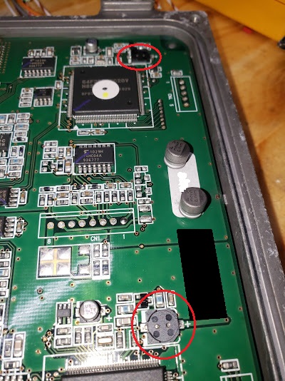
I recently experienced a situation where an engine ECU failed. The post-failure analysis showed that two capacitors had broken loose from the board due to stress from vibration. I have replaced the capacitors, but without any changes, I assume that this will happen again. How can I provide proper mechanical support for these?

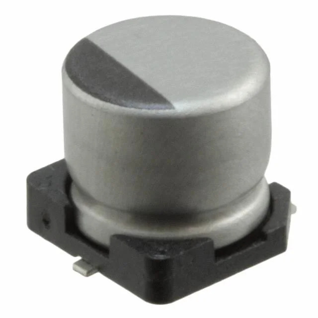
Edit: the capacitors are Nichicon UUT1V220MCL1GS

enter image description here

enter image description here

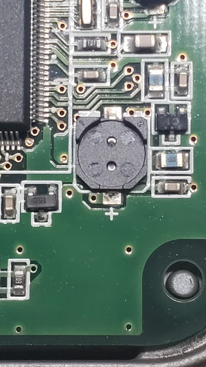
enter image description here

\$\endgroup\$
7
  • \$\begingroup\$ It’s a tricky one because, do you blob some epoxy around them but, in doing so make them more vulnerable to pulling PCB tracks up at a different resonant frequency or, just the same happens at the new resonant frequency. If you can measure the values or see the values I’d consider replacing with SMD devices. \$\endgroup\$
    – Andy aka
    Commented Feb 6, 2020 at 18:18
  • \$\begingroup\$ It would be helpful if we could see what the capacitors look like before they fail. \$\endgroup\$ Commented Feb 6, 2020 at 19:07
  • \$\begingroup\$ @Andyaka, the capacitors that broke of were SMD parts (Nichicon UUT1V220MCL1GS). What would you replace them with? This is an OEM board, so I can't change the pads... \$\endgroup\$ Commented Feb 6, 2020 at 19:07
  • \$\begingroup\$ @ElliotAlderson, the capacitors are Nichicon UUT1V220MCL1GS \$\endgroup\$ Commented Feb 6, 2020 at 19:07
  • \$\begingroup\$ I’d fix them to the broken fixings and use 1206 x7r types but it’ll still need glue and possibly several devices. What value? \$\endgroup\$
    – Andy aka
    Commented Feb 6, 2020 at 19:09

4 Answers 4

1
\$\begingroup\$

RTV silicone is used for this (and to adhere components to PCBs permanently in general). The neutral cure kind that doesn't produce acetic acid and smell like vinegar when it cures. So not most of the stuff you will find in hardware stores.

RTV-162 is one of the purpose-designed silicones for this but it's almost more than double the cost of some other neutral cure alternatives like RTV-108 or RTV-6708. From comparing the datasheets, the main difference appears to be that RTV-162 is twice the hardness and strength.

\$\endgroup\$
6
  • \$\begingroup\$ I don't think RTV will help with the breakage from the board, though it may keep the part in place. A rigid structural adhesive is needed here, IMO. \$\endgroup\$
    – SteveSh
    Commented Feb 6, 2020 at 20:09
  • \$\begingroup\$ @SteveSh Did I misunderstand something? The RTV silicone is used so it takes the load off of whatever would have otherwise taken the load. \$\endgroup\$
    – DKNguyen
    Commented Feb 6, 2020 at 20:36
  • \$\begingroup\$ I may be wrong, but I don't think any compliant material will help with the stress that's causing the part to break off the board. The stresses from vibration are caused by the inertia of the component. The component really isn't moving very much, if at all, relative to the PCB, during vibe, until it breaks. I'm not a structural analyst so can't say for certainty, but I do know that we don't use RTV or anything similar in that kind of application. \$\endgroup\$
    – SteveSh
    Commented Feb 6, 2020 at 20:51
  • \$\begingroup\$ @SteveSh My understanding that was RTV was stiff enough to do the job, but not so hard that it would stress the solder joints from things like thermal expansion or curing (which is why I heard epoxy was not so good). Isn't it used to glue things like big capacitors, inductors, and transformers to protect the solder joints. \$\endgroup\$
    – DKNguyen
    Commented Feb 6, 2020 at 21:01
  • 2
    \$\begingroup\$ Silicone is useful as it absorbs the energy of the vibration, damping the resonance, so that the displacement is prevented from becoming so extreme that fatigue occurs. It it this benefit, rather than a structurally stiff characteristic that provides the most improvement. \$\endgroup\$
    – elchambro
    Commented Feb 6, 2020 at 21:39
1
\$\begingroup\$

Perhaps looking at the case, you can add some thick tape or something else that you come up with to the top part, which would push down on the capacitor (gently), since the case will be vibrating the same direction as the PCB it should be fine.

\$\endgroup\$
1
\$\begingroup\$

Interesting failure, and not surprising when you feel how loose the bases often are.

I think you'd be more than fine with a couple drips of epoxy or non-acidic RTV silicone between the can and the plastic base before the cap is mounted. Personally, I'd use 5-minute cure dollar store epoxy.

\$\endgroup\$
1
\$\begingroup\$

We use some sort of structural adhesive for these kinds of applications, where staking is required.

Since this is for a high-volume ECU, I assume the proper structural/vibration analysis was done? If so, the first thing you need to do is go back to that analysis analysis and figure out where the disconnect is between the model and the real world. Then you will be in better position to ascertain whether staking is a way out of your problem.

EDIT 1 - Added typical vibe profile

The plot below is what comes out of a properly done vibration analysis. The colors represent the amount of deflection, with blue being the smallest (the board being constrained along its edges), and red the highest. A structural engineer then takes the mass properties of the components, the amount of movement and frequency (which are used to compute the G forces) and figures out what the stresses are, and where.
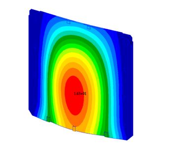
enter image description here

Lacking such an analysis, you're left with just using guesses as to what kind, where, and how much adhesive to use.

\$\endgroup\$

Your Answer

By clicking “Post Your Answer”, you agree to our terms of service and acknowledge you have read our privacy policy.

Not the answer you're looking for? Browse other questions tagged or ask your own question.