4
\$\begingroup\$

I am in the process of designing a PCB that is powered by a 10V / 1mA supply from a fandeck (incorporating EC/DC fan motors).

One of the functionalities include having continuity between 2 pins on the PCB (Volt free contacts), which are connected to an external controller (Master). Since the supply can only supply 1mA, I am using 2 n-channel Mosfets for their high input resistance. However, I don't know how to switch them since they're connected to an external circuitry with different voltage references (grouds), and the mosfet switching works around the gate to source voltage (Vgs(Threshold)).

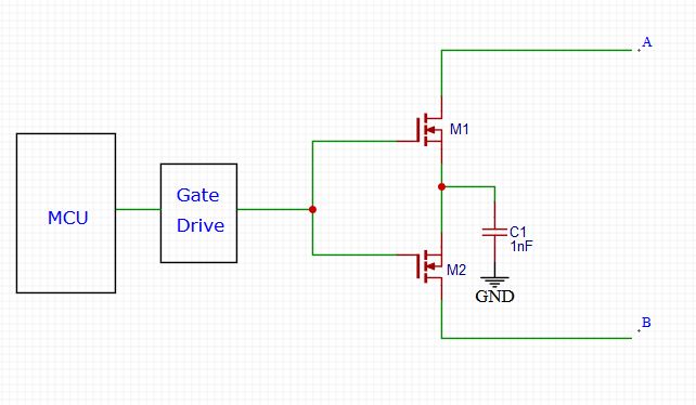
One idea I had was to connect the Mosfet sources together and put a 1nF cap to ground so the voltage from the MCU would be with reference to both sources of the mosfets. enter image description here
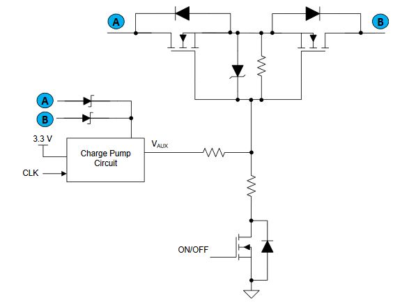
I also saw the attached picture in an application note from Texas Instruments (Application Report SLVA948–December2017), But I don't have any prior experience with charg pumps and am a little bit worried regarding their current draw and I also don't know the voltages that master controller might exert to check continuity so i don't know how higher the voltage should be when fed into the gates.
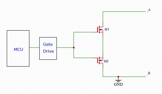
One other thing that comes to mind is just connecting one of the contacts to ground (PCB ground), However I am not certain this would work either. enter image description here
I am already familiar with gate drive design so that is not an issue. Is there a better way of doing this with less current draw? any help would be highly appreciated.

Many thanks in advance for your time.

\$\endgroup\$
3
  • \$\begingroup\$ What voltage is your gate drive circuit running at? And more importantly, what voltages are you encountering at A and B? Do they have a common ground or are they floating? How much current do you expect to flow when they're connected? \$\endgroup\$ Commented Feb 14, 2020 at 13:26
  • \$\begingroup\$ Hi @CristobolPolychronopolis , the gate drive is driven with a 3.3V regualted voltage. As for A and B, they sometimes get connected across a common pin and a digital output, and as they are volt free contacts I think it would have about 12V dc across it. However, in some other cases, they are just connected acroos 2 GPIOs. But I am certain the current would not exceed 7.5 mA. \$\endgroup\$
    – NeuroEng
    Commented Feb 14, 2020 at 14:27
  • \$\begingroup\$ You can also just use little isolated SMPS supplies. They are about $5 a pop. \$\endgroup\$
    – DKNguyen
    Commented Feb 14, 2020 at 22:37

2 Answers 2

2
\$\begingroup\$

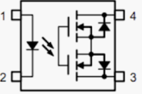
If you are able to convert this 10V/1mA (1) to a bit more mA @ 1V or 2V you may want to consider using a "photovoltaic relay" or "solid state mosfet relay":

enter image description here where pins 3 and 4 are the isolated terminals A and B.

You should check the maximum required "trigger forward current" or "the minimum control current" or whatever description that tells you which current you need worst case to turn on the internal LED.

In my small research I found a few that need about 2 to 5 mA. The G3VM only needs 0.2 mA typical and worst case 3 mA.

(1) It's not clear to me, but it seems this 3V3 regulator mentioned in the comments is such an example.

\$\endgroup\$
1
  • \$\begingroup\$ Hi @Huisman, I am currently using a 3.3V LVD with ultralow operating current (<1uA), I also though of using a switching regulator that does exactly what you said (stepping the voltage down while the curernt increases), how ever switching supplies draw massive currents in short intervals and I am worried that this might cause damage to the supply. I tried using a limiting resistor, this how ever would cause voltage drop at the output. I think I have hit a stone wall! :))) \$\endgroup\$
    – NeuroEng
    Commented Feb 17, 2020 at 10:44
0
\$\begingroup\$

If the required signal rate is slow slow enough, use the 1mA to charge a capacitor and when needed dump the capacitor through a latching relay's appropriate coil.

\$\endgroup\$

Your Answer

By clicking “Post Your Answer”, you agree to our terms of service and acknowledge you have read our privacy policy.

Not the answer you're looking for? Browse other questions tagged or ask your own question.