I am in the process of designing a PCB that is powered by a 10V / 1mA supply from a fandeck (incorporating EC/DC fan motors).
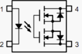
One of the functionalities include having continuity between 2 pins on the PCB (Volt free contacts), which are connected to an external controller (Master). Since the supply can only supply 1mA, I am using 2 n-channel Mosfets for their high input resistance. However, I don't know how to switch them since they're connected to an external circuitry with different voltage references (grouds), and the mosfet switching works around the gate to source voltage (Vgs(Threshold)).
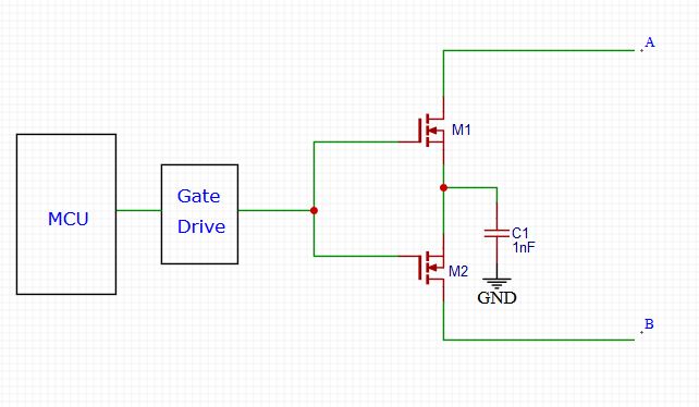
One idea I had was to connect the Mosfet sources together and put a 1nF cap to ground so the voltage from the MCU would be with reference to both sources of the mosfets. 
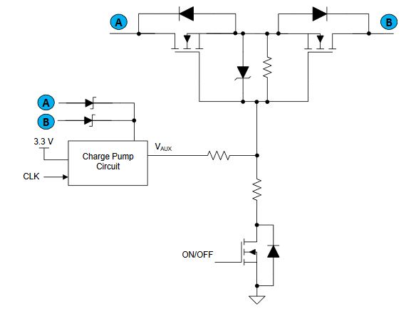
I also saw the attached picture in an application note from Texas Instruments (Application Report SLVA948–December2017), But I don't have any prior experience with charg pumps and am a little bit worried regarding their current draw and I also don't know the voltages that master controller might exert to check continuity so i don't know how higher the voltage should be when fed into the gates.
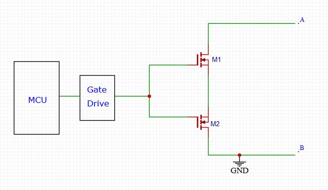
One other thing that comes to mind is just connecting one of the contacts to ground (PCB ground), However I am not certain this would work either. 
I am already familiar with gate drive design so that is not an issue. Is there a better way of doing this with less current draw? any help would be highly appreciated.
Many thanks in advance for your time.

