0
\$\begingroup\$

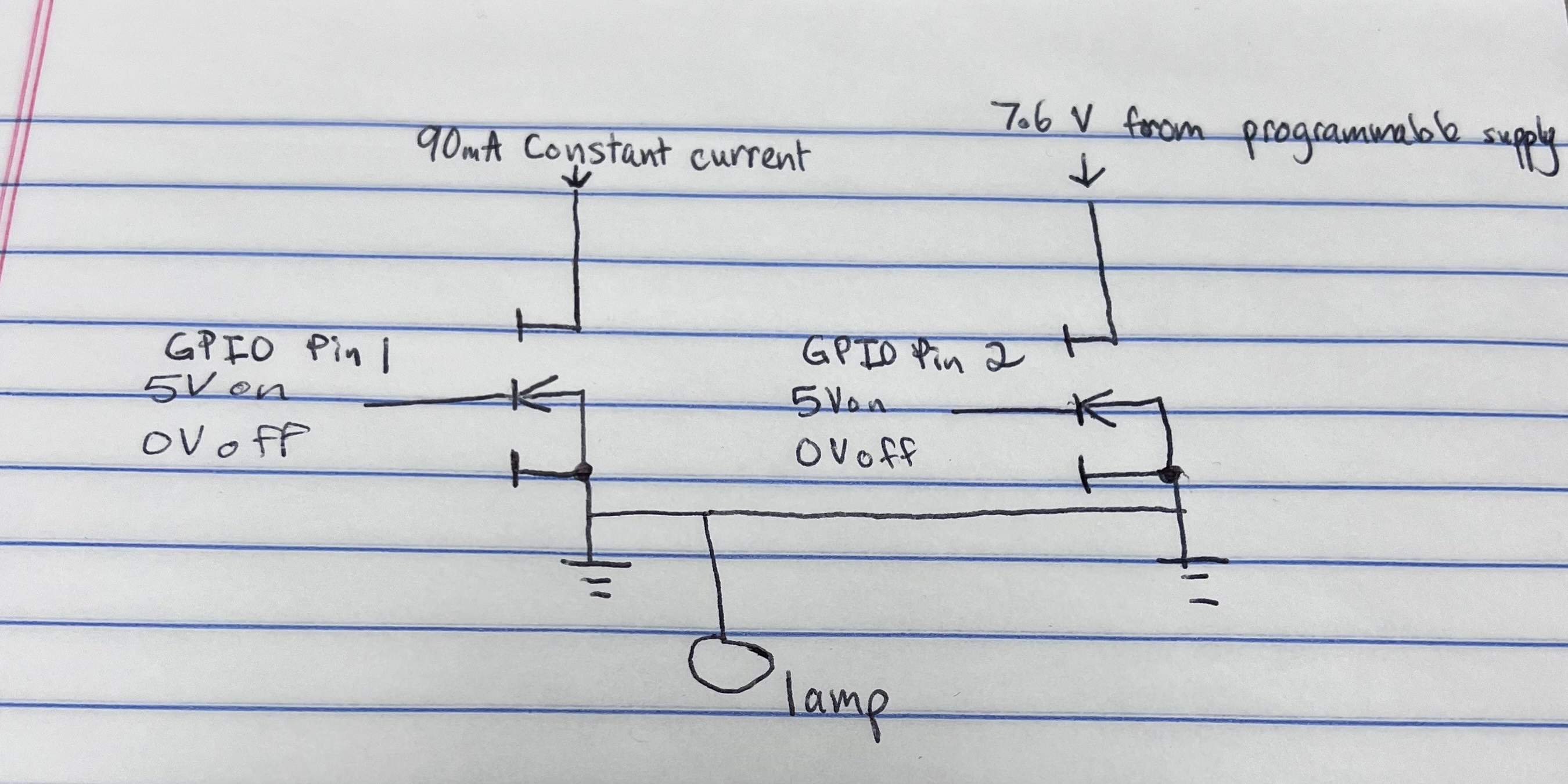
I need to switch between a constant current source and a programmable power supply to power a lamp.

For both sources, I need to apply 7.6 V to the drain and have the 7.6 V outputted to the lamp. The gates of the two MOSFETs will be controlled with two seperate GPIO pins. So when a logic HIGH level is applied to the gate of one MOSFET from the GPIO pin, the first source will be used and the other MOSFET would be off.

I have attached an image of the concept that I had in mind. I know the circuitry is incorrect but I was wondering if anyone knew the best way to do this.

Please note that I don't want to use relays.

Circuit Concept

\$\endgroup\$
1
  • 1
    \$\begingroup\$ Neg prog source and Negative constant current source are both shorted to ground. Either fix that or remove them both and substitute with just ground. Same goes for lamp in your hand-draw example. I believe you want your lamp high side and keep all switching on the low side. \$\endgroup\$
    – winny
    Commented Jan 6, 2023 at 20:03

1 Answer 1

2
\$\begingroup\$

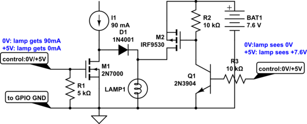
The safer way to switch a 90 mA current source ON/OFF with a N-channel MOSFET is shown below. One should ensure that M1's drain-to-source breakdown voltage exceeds the open-circuit current source voltage.
schematic

simulate this circuit – Schematic created using CircuitLab

Be aware that control of MOSFET gate is opposite of OP's wishes... 90 mA is directed to the lamp when M1 gate is at 0V. When MOSFET gate is +5V, the MOSFET shunts 90 mA to GND rather than through the lamp. R1 is included to keep M1 firmly off if no control voltage is attached to M1's gate. So default operation allows 90 mA to the lamp.


A P-channel MOSFET (M2) more easily switches the +7.6V BAT1 voltage source. However, its gate cannot be driven directly from a GPIO pin that can only rise to +5V. A small transistor (Q1) does the switching. If R3 is left open-circuit, Q1 is off, M2 as well.

Caution:
If M1's control voltage is 0V, and Q1's control voltage is +5V, you get undefined operation - avoid this condition. If no lamp exists, or burns out, the 90 mA source will try to charge BAT1. OP says that BAT1 is a "programmable voltage source" (which is certainly not a battery). Many such voltage sources mis-behave if you try to charge them - bad things could happen.

GND symbol shown must also extend to GPIO's microcontroller GND too.

\$\endgroup\$
0

Your Answer

By clicking “Post Your Answer”, you agree to our terms of service and acknowledge you have read our privacy policy.

Not the answer you're looking for? Browse other questions tagged or ask your own question.