0
\$\begingroup\$

I want to understand how can I make a crystal oscillator circuit with a 2 pin oscillator.

I did some research and I have this from this website (section Crystal Oscillator Circuit) : enter image description here
Or same on this one (section Crystal Oscillator Circuit Diagram) : enter image description here

I don't understand at all which values of resistors;capacitor do I need to use neither how to calculate them...

Second of all if someone can also explain to me why this second blue schematic on the right in the picture above...

Finally I did this screen from this YouTube video where the crystal seems need to be on the left: enter image description here
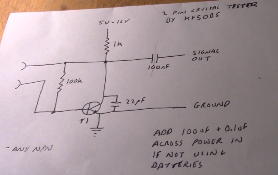
So I'm a little bit lost...Can you please explain to me those three things (first schematic; second blue schematic and why this totally different schematic - which seems working as we can see later in the video - from the YouTube video)?

Thank you very much !

EDIT

@Bimpelrekkie I just want a sine output and that's it nothing more. As I can see on your link they're talking about square wave even if he said that "The first inverter really produces a analog signal.It will be more of a sine wave than a square wave" it won't be a clean sine on the output am I right ? They gave values for given frequencies, how did they calcute those values ? For example 12.288MHz, what are the values for C and R2 ?

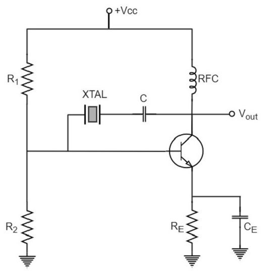
@Fredled Thanks to your link it seems that I will need a Pierce Crystal Oscillator : enter image description here
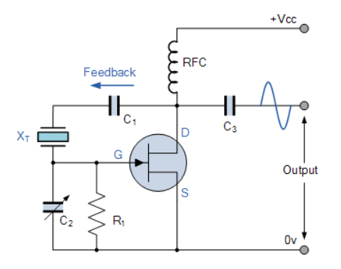
My question is still here, how can I know the values for those capacitors ; R1 and radio frequency choke...

\$\endgroup\$
6
  • \$\begingroup\$ Do you insist on using this type of circuit (with one NPN)? Because if you just want a crystal oscillator there are simpler solutions, see this question: electronics.stackexchange.com/questions/218142/… I see "crystal tester" written there, then for sure I would use one of those circuits as the single NPN circuit might not work with some crystals while the circuits using inverters work with almost any crystal. \$\endgroup\$ Commented Mar 29, 2020 at 20:41
  • \$\begingroup\$ The inverter based circuits have more signal gain than a single transistor will ever have and that makes it much easier to get the circuit to oscillate. \$\endgroup\$ Commented Mar 29, 2020 at 20:44
  • \$\begingroup\$ Depending on your application, chose the easiest variant here: electronics-tutorials.ws/oscillator/crystal.html \$\endgroup\$
    – Fredled
    Commented Mar 29, 2020 at 21:03
  • \$\begingroup\$ Thanks for your answers, see my edit please \$\endgroup\$
    – Julionabi
    Commented Mar 30, 2020 at 8:18
  • \$\begingroup\$ Your crystal oscillator examples do not make pure sinewave, the waveform can be quite complex. Radio amateurs use crystal oscillator shortwave transmitters. They are also used in simplest possible 27MHz walkie talkies which work in single fixed channel. The waveform must be reasonably clean sine because the power of harmonic components must be low due the frequency usage regulations. A resonant circuit can clean the waveform substantially. Here's a walkie talkie schematic electronics.stackexchange.com/questions/487231/…. \$\endgroup\$
    – user136077
    Commented Mar 30, 2020 at 8:48

2 Answers 2

1
\$\begingroup\$

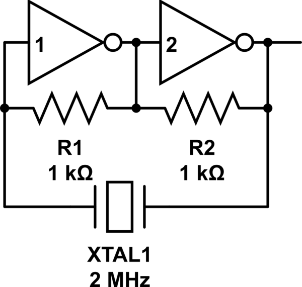
The easiest approach I have found and used is with just two inverters:

schematic

simulate this circuit – Schematic created using CircuitLab

I have built this with a 74LS04 with no problem at all. It is trivial. No calculations of RC networks required. 2MHz and 4MHz both worked. I am going to experiment with a Schmitt trigger-inverter to follow to see if that makes the wave more of a rectangle.

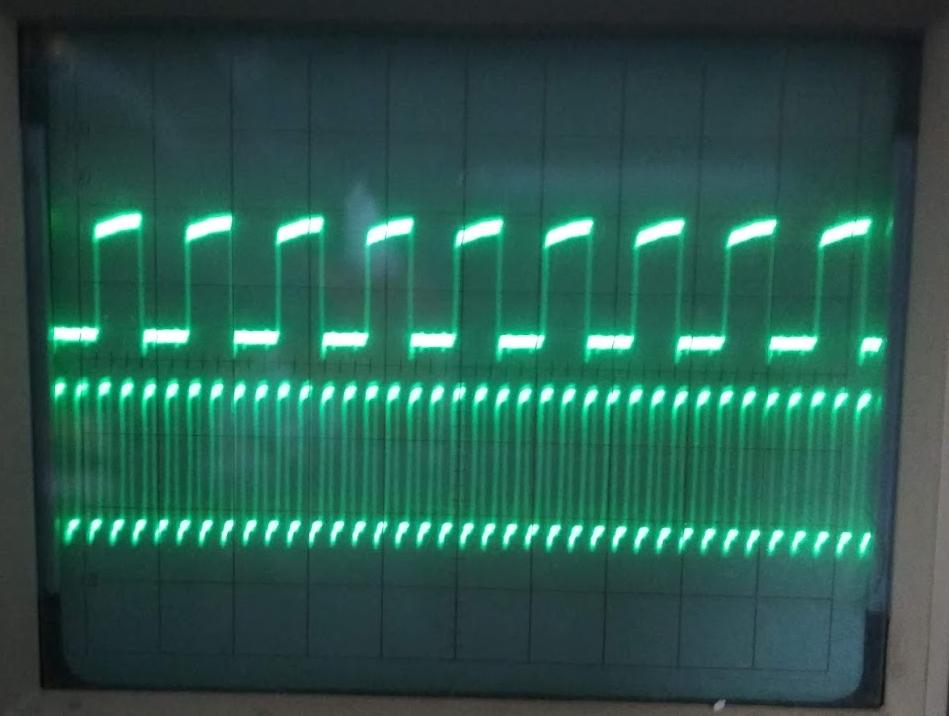
My scope picture shows what I am getting and I use a 74LS161 counter to divide the frequency down and I see the forms are all the same: a little down spike right before the rising edge and then a bit of an up-slope of the roof of the wave. I think that's mostly determined by my use of bread board.

enter image description here

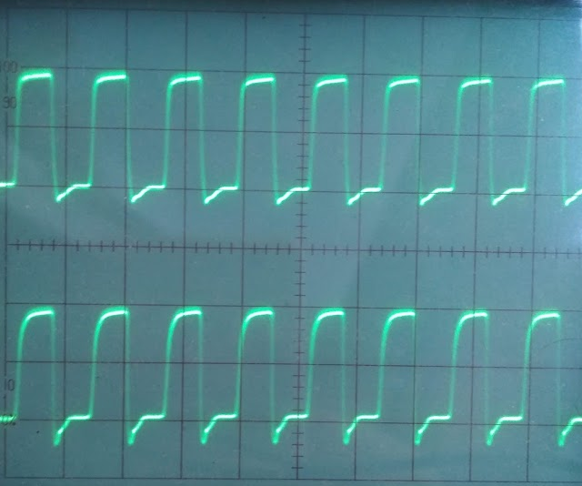
UPDATE: Here are the results of another experiment where I follow this simple clock generator with a Schmitt-trigger to see if it forms any prettier rectangles. Above the output of a regular additional inverter stage, and below if that additional inverter stage is a Schmitt-trigger. If anything the regular inverter produces prettier rectangles.

enter image description here

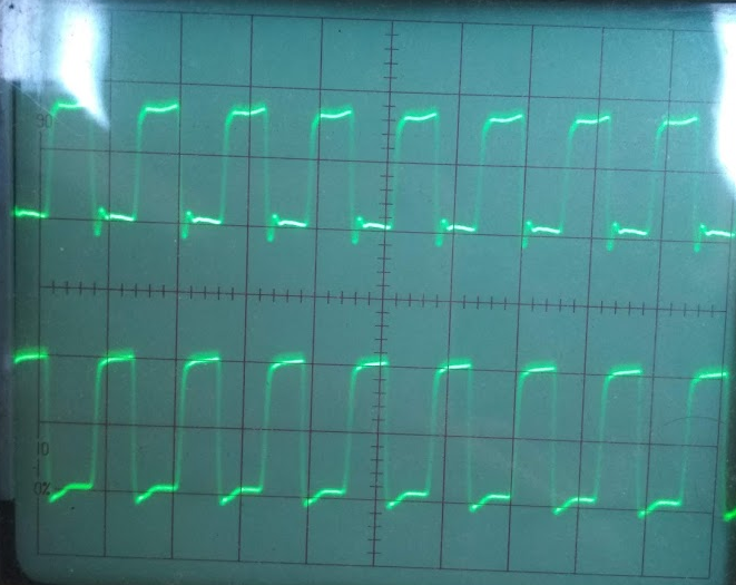
Here is the direct output from the inverter 2 of the oscillator vs. the output of an additional regular inverter. Cleans up this overshooting down-stroke a little.

enter image description here

One thing that makes me puzzled is the frequency I am getting here. I don't know if my calculations are off, but it looks to me that the period duration is just a little over one scope division, and to be more exact I have pretty exactly 4 periods in 5 scope divisions. And the setting is at 0.1 μs per division, so that would mean 0.5 μs / 4 periods or T = 0.125 μs, for an f = 8 MHz! How can it be that a 2 MHz crystal produces 8 MHz oscillations? This is very puzzling. It means I need to try out other circuits to understand this.

\$\endgroup\$
0
\$\begingroup\$

To proceed further in your understanding, read up on PI filters.

Given the circulating currents within a PI filter, the opposite ends are at opposite polarity, which allows Invertinng amplifiers to be used.

Additionally, the two capacitors in a CLC PI filter need not be the same value; this allowed a stepup voltage or allows "impedance matching" for some circuits.

\$\endgroup\$

Your Answer

By clicking “Post Your Answer”, you agree to our terms of service and acknowledge you have read our privacy policy.

Not the answer you're looking for? Browse other questions tagged or ask your own question.