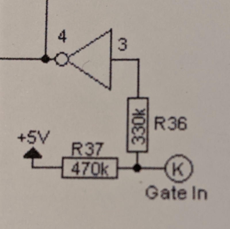
I'm trying to understand part of an envelope generator circuit. Here's the part of the schematic for the GATE IN, marked by the K, which can accepts a signal of between 0V and +5V.
I understand that the 470k resistor is a pullup resistor which will keep the NOT gate (a CD4069 hex inverter with a +5V supply voltage) input pin high if there is no signal from the gate.
What's the purpose of the 330k resistor though? Why shouldn't I just connect K directly to the input pin?
Update: More details on the GATE IN signal.
This circuit is intended to be used in a modular synthesizer. The GATE IN control voltage is expected to trigger the attack stage of the envelope generator at +5V and the release stage at 0V.
There shouldn't be any other values presented to GATE IN. However, other voltages present in modular sythesizers typically range from -15V to +15V, and with some effort (to break things) could be presented to GATE IN.

