Polarized capacitors can handle about 10% of the rated voltage in the reverse direction.
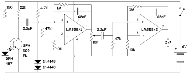
Tantalum tend to have lower Series resistance such as 10 ohms in this small value in a small size. Since the capacitor has a high impedance load (47K in parallel with + OpAmp) any capacitor will work. use any Ceramic, alum, tantalum and may vary in price from 10 cents and up. /1pc) choose a voltage rating >2x what you need for margin. e.g.
The smaller caps can be ceramic.
If you want to prevent minor reverse leakage of a polarized cap in this circuit, the + side would be on the input which is pulled up to 6V than it sees - 1V across it when the optotransistor clamps to 0.3V while the two diodes are 1.3V.
The design is not optimal, but should be enough to drive a small LED and pulse with the heart rate. ( eg RED LED and 470~ 1K ohm )
Editorial note: I agree the comments are confusing considering no polarity given and actually irrelevant since ESR is not important so it reflects a weak design skills.
Also the IRT photo-transistor does not have a dark daylight blocking filter tint, so the design will be sensitive to flicker of bright 120Hz fluorescent lights. I would suggest a different part in surface mount or thru hole. You can use any IR LED that comes in remote controllers.
The 6V battery may drain quickly and need a switch and perhaps a large cap across to suppress ripple that the weak battery may create.

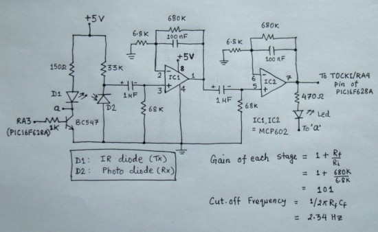
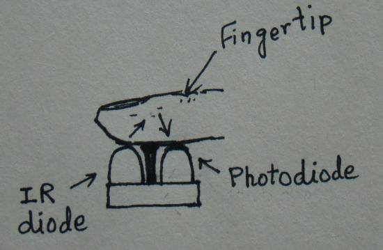
This improved design uses reflective light rather than transmissive IR light. It uses photo diodes instead of transistors so no pot is needed as the tolerances are much tighter.
Same gain and filter is used but different values. It uses operational amplifier MCP602 which operates rail to rail without bias diodes and can run on 6V easily or 5V if you prefer.
In any case, the leads must be short or else you must use ferrite
choke around the twisted pair to suppress 60Hz hum interference on the detector &
the hand acts as an antenna to this signal.

**


